A guiding and clamping mechanism for a syringe pump

A clamping mechanism and a technology for a syringe pump, applied in the field of syringe pumps, can solve the problems such as the inability to apply syringes of different specifications and the limitation of the use range of the syringe pump.

Active Publication Date: 2021-07-02
柏威医疗(阜阳)有限公司
View PDF7 Cites 0 Cited by
  • Summary
  • Abstract
  • Description
  • Claims
  • Application Information

AI Technical Summary

Problems solved by technology

The guide and clamping mechanism of the existing syringe pump cannot be applied to syringes of different specifications, and it is necessary to replace the syringe pump of different specifications, which limits the scope of use of the syringe pump. Therefore, a guide and clamping mechanism for syringe pumps is designed and produced here. in order to solve the above problems

Method used


Image

  • A guiding and clamping mechanism for a syringe pump
  • A guiding and clamping mechanism for a syringe pump
  • A guiding and clamping mechanism for a syringe pump

Examples


Embodiment 1

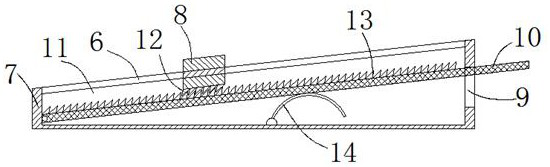
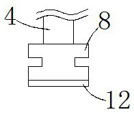
[0019] see Figure 1-3 , the present embodiment provides a guiding and clamping mechanism for an injection pump, comprising a mounting base 5 and two guiding bases 7, the guiding bases 7 are respectively fixed on the front and rear ends of the mounting base 5, and the top end surfaces of the two guiding bases 7 A 30-degree sliding slope is provided, and the left end is lower than the right end. The inner cavities of the two guide seats 7 are provided with a sliding cavity 11, and the top sliding slopes of the two guide seats 7 are provided with a sliding gap 6 communicating with the sliding cavity 11. The right end faces of the two guide seats 7 are all provided with a rectangular notch 9 communicating with the sliding cavity 11, and the inner cavities of the two sliding notches 6 are all slidably provided with an I-shaped slider 8, and the two I-shaped sliders 8 The bottom end faces are extended with locking teeth 12, and the left end faces of the inner chambers of the two sl...

Embodiment 2

[0023] see Figure 1-3 , further improvements have been made on the basis of Example 1:

[0024] The two I-shaped sliders 8 are respectively attached to the upper and lower side walls of the opening of the two sliding notches 6, and a freely rotatable steel ball is embedded in the joint position of the I-shaped slider 8 and the side walls of the opening of the sliding notch 6 , by arranging freely slidable steel balls, the friction force when the I-shaped slider 8 slides left and right can be reduced.

[0025] The bottom end surface of the arc-shaped positioning clamping plate 1 is extended with a plurality of evenly spaced convex points. By setting the convex points, it is convenient to clamp the side wall of the syringe and realize the positioning of the syringe.

[0026] The left end surface of the arc-shaped positioning clamp 1 is horizontally provided with an upwardly curved guide arc-shaped plate 3. By setting the guide arc-shaped plate 3, it is convenient to assist in ...


PUM


Abstract

The invention discloses a guiding and clamping mechanism for a syringe pump, comprising a mounting seat and two guiding seats, the guiding seats are respectively fixed on the front and rear end surfaces of the mounting seat, the inner cavities of the two guiding seats are provided with sliding cavities, and the two guiding seats are provided with sliding cavities. The top sliding slopes of the guide seats are provided with sliding gaps that communicate with the sliding cavity, the right end surfaces of the two guide seats are both provided with rectangular gaps that communicate with the sliding cavities, and the inner cavities of the two sliding gaps are slidably provided with I characters. The left end face of the inner cavity of the two sliding cavities is equipped with an adjusting plate that can swing up and down around the rotation point. Vertically distributed uprights are welded to the center of the top surface of the I-shaped slider, and a cross beam is welded between the top surfaces of the two uprights. The invention is convenient for matching and clamping syringes of different specifications, so as to meet the normal use requirements, and is simple and practical.

Description

technical field [0001] The invention relates to the related technical field of syringe pumps, in particular to a guiding and clamping mechanism for syringe pumps. Background technique [0002] The syringe pump is composed of a stepping motor and its driver, a screw and a bracket, etc., and has a reciprocating screw and a nut, so it is also called a screw pump; the nut is connected with the piston of the syringe, and the drug solution is contained in the syringe to achieve high Precision, smooth and pulsation-free liquid transfer. The guide and clamping mechanism of the existing syringe pump cannot be applied to syringes of different specifications, and it is necessary to replace the syringe pump of different specifications, which limits the scope of use of the syringe pump. Therefore, a guide and clamping mechanism for syringe pumps is designed and produced here. In order to solve the above problems. Contents of the invention [0003] The purpose of the present invention...

Claims


Application Information

Patent Timeline
Patent Type & Authority Patents(China)
IPC IPC(8): B23Q3/00A61M5/20A61M5/42
CPCA61M5/008A61M5/20A61M5/42
Inventor 欧阳嘉琪
Owner 柏威医疗(阜阳)有限公司
Why Eureka
Try Eureka