
Commutation failure early detection and prevention method and device and application thereof

A technology of commutation failure and prevention method, which is applied in the direction of measuring device, measuring electricity, measuring electrical variable, etc., can solve the problems of poor control effect of commutation failure, unfavorable commutation failure, overshoot or undershoot, etc.

Active Publication Date: 2019-11-29
NORTH CHINA ELECTRIC POWER UNIV (BAODING) +1
View PDF3 Cites 4 Cited by
  • Summary
  • Abstract
  • Description
  • Claims
  • Application Information

AI Technical Summary

Problems solved by technology

[0005] Such as the prior art Chinese patent application (application number: CN2013105773783), which discloses a method for judging commutation failure caused by the coupling effect of multiple DC lines paralleled on the same tower. side of the maximum sudden change current △I f.max Calculate the maximum commutation time area A provided by the power grid and the commutation area B required for successful commutation, and judge the occurrence of commutation failure by comparing the size of A and B; When using the real-time data after the failure, the early detection of commutation failure is slow, which is not conducive to preventing the occurrence of commutation failure
[0006] For example, the prior art Chinese patent application (application number: CN2014108011644) discloses a method for increasing the value of the arc extinguishing angle according to the value of the DC commutation failure. , according to the value of the commutation area, set the value of the arc extinguishing angle required to increase the arc extinguishing angle control operation; in this method, there is no physical model constraint between the value of the commutation area and the increased arc extinguishing angle angle. The values ​​of the parameters k and b in the fault situation are obtained from experience. Under the action of the control system, overshoot or undershoot is easy to occur, which in turn aggravates the impact of commutation failure.
[0007] For example, the Chinese patent application (application number: CN2018100385549) in the prior art discloses a control method for reducing the continuous commutation failure of HVDC power transmission system. The method samples the DC current and the AC voltage of the inverter side in real time to calculate the commutation failure. Value at risk F 0 , through the risk value F 0 Calculate the DC current control reference value, and then control the DC current to reduce the continuous commutation failure; but this method is to calculate the real-time measurement of the electrical quantity after the fault, and the inverter side is already in the commutation stage during the process, and the obtained control As a result, the control effect on commutation failure is poor, and the occurrence of commutation failure cannot be detected in advance

Method used

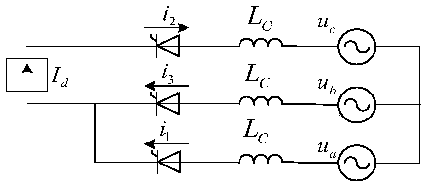
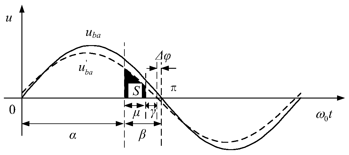
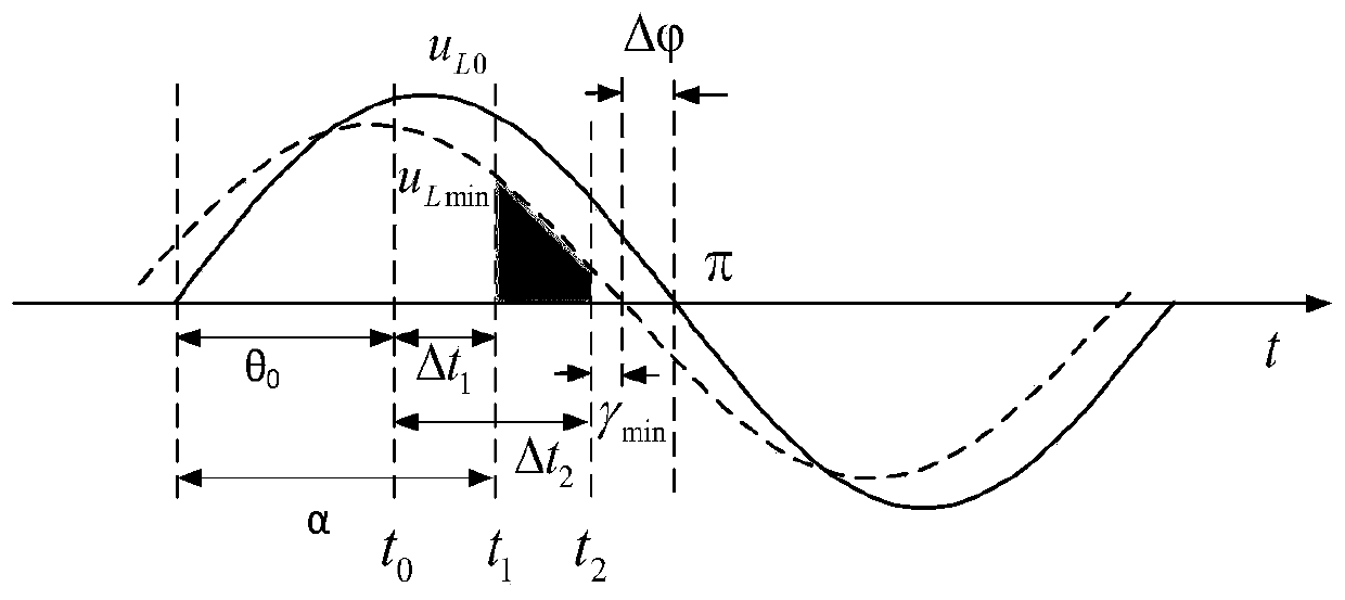

Image

  • Commutation failure early detection and prevention method and device and application thereof
  • Commutation failure early detection and prevention method and device and application thereof
  • Commutation failure early detection and prevention method and device and application thereof

Examples


Embodiment 1

[0084] In this embodiment, the effectiveness of the method for early detection of commutation failure is tested under the conditions of single-phase ground fault and three-phase ground fault respectively. The specific method is as follows:

[0085] In a single-phase ground fault, set 5.001s when the AC bus on the inverter side occurs f =0.88H excessive resistance grounding fault, the fault duration is 50ms, where S need -S min is the commutation area difference output by the commutation area calculation unit; CFPS is the commutation failure detection signal, whose value changes from 0 to 1, and detects that the commutation failure is about to occur in the system in advance; angle, the simulation results are as follows Figure 7 shown. It can be seen from the figure that the commutation failure early detection algorithm proposed by the present invention is under the normal operation of the DC system, S need -S min is always less than 0, judging that commutation failure doe...

Embodiment 2

[0090] In this embodiment, the effectiveness of the quantitative firing angle control strategy based on the critical commutation area is tested under different fault types. The specific method is as follows:

[0091] Set single-phase ground fault, phase-to-phase fault and three-phase fault on the commutation bus on the inverter side respectively, and count the occurrence of the CIGRE standard test model and the early detection control model based on the critical commutation area under different time and different degree of fault conditions In case of commutation failure. Among them, single-phase ground fault takes A-phase ground fault as an example; phase-to-phase short-circuit fault takes B and C two-phase short-circuit as an example. The statistical results are shown in Figure 11; it can be seen from the figure that under different types of AC side faults, the detection control model reduces the grounding inductance value of the critical commutation failure, indicating that ...


PUM


Abstract

The invention discloses a commutation failure early detection and prevention method and device and an application thereof. An existing commutation failure detection method still has the problems of low response speed of a control system, excessive dependence on simulation calculation, lack of physical model support and theoretical basis, insufficient universality and the like. The voltage waveformafter a fault is quickly fitted out through a three-point method, and a supplied minimum commutation area is calculated; a demanded commutation area is compared with the supplied minimum commutationarea, and communication failure detection is carried out in advance; and measures are taken according to a detection result to prevent commutation failure. According to the invention, commutation failure can be detected in advance, an effective signal can be provided for DC control, commutation failure can be prevented, the calculation amount is small, the speed is high, and the method and the device are not influenced by the fault type and the fault time.

Description

technical field [0001] The invention belongs to the technical field of electric power system relay protection, and relates to a method and device for early detection and prevention of commutation failure. Background technique [0002] Traditional high-voltage direct current transmission has the characteristics of large transmission capacity, strong power regulation ability, and relatively low cost. However, the core component of this transmission technology, the thyristor, has no self-shutoff capability, which leads to insufficient voltage support for the AC system on the inverter side. In this case, commutation failure is very likely to occur. The failure of commutation will not only cause a surge in DC current and impact on the converter valve, but also cause large fluctuations in DC power. In severe cases, it may even cause the DC system to be blocked. The safe and stable operation brings a more severe test, and its preventive measures are mainly divided into two aspects...

Claims


Application Information

Patent Timeline
IPC IPC(8): H02J3/36G01R31/00
CPCH02J3/36G01R31/00Y02E60/60
Inventor 王增平郑博文刘席洋崔勇赵乐张开宇
Owner NORTH CHINA ELECTRIC POWER UNIV (BAODING)
Learn More