A headless bearing type centrifugal main engine of a centrifugal pipe casting machine

A technology of centrifugal casting pipe and headless technology, which is applied in the field of mechanical equipment, can solve the problems of inability to process pipe fittings and pipe fittings, etc., achieve high production efficiency, reduce investment, and realize the effect of automatic adjustment

Active Publication Date: 2021-11-23
杭州春风机械工程股份有限公司
View PDF9 Cites 0 Cited by
  • Summary
  • Abstract
  • Description
  • Claims
  • Application Information

AI Technical Summary

Problems solved by technology

[0002] The centrifugal main engine of the centrifugal pipe casting machine is used in the processing of ductile iron pipes. During the processing of ductile iron pipes, molten iron needs to be poured into the pipe mold. The centrifugal main engine drives the pipe mold to rotate at a high speed, so that the molten iron is formed in the pipe mold and cooled. Casting into pipe fittings, before pouring molten iron into the pipe mold, it is necessary to block the socket end of the pipe mold with a sand core to prevent the molten iron used in pouring from flowing out, and then pour molten iron into the pipe mold from the socket end of the pipe mold to process the pipe. For pipe fittings with a diameter of less than 1200mm, the socket end of the pipe mold is supported by bearings, and pipe fittings with a diameter of less than 1200mm cannot be processed
[0003] In view of this, a centrifuge dedicated to pouring ductile iron pipes is disclosed in the patent document with the announcement number 201621484921.0. The centrifuge in the above reference document is suitable for processing pipe fittings with a pipe diameter of 1200mm or less, and cannot process pipe fittings with a pipe diameter of 1200mm or more. pipe fittings

Method used


Image

  • A headless bearing type centrifugal main engine of a centrifugal pipe casting machine
  • A headless bearing type centrifugal main engine of a centrifugal pipe casting machine
  • A headless bearing type centrifugal main engine of a centrifugal pipe casting machine

Examples


Embodiment Construction

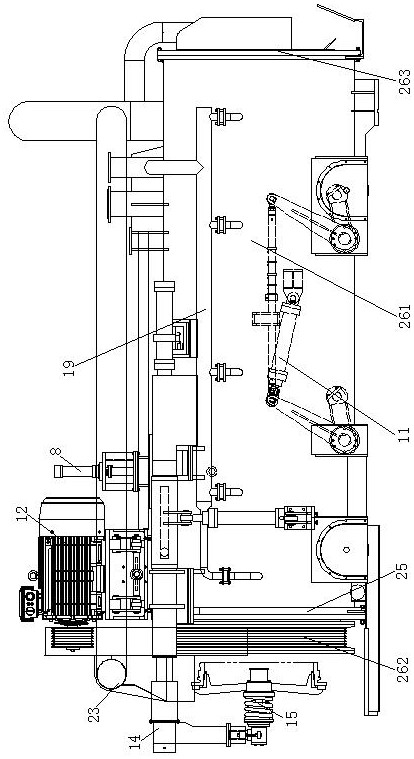
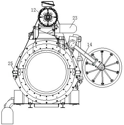
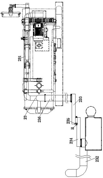
[0105] The present invention will be further described in detail below in conjunction with the accompanying drawings and examples. The following examples are explanations of the present invention and the present invention is not limited to the following examples.

[0106] Example.

[0107] see Figure 1 to Figure 19 It should be noted that the structures, proportions, sizes, etc. shown in the drawings attached to this specification are only used to match the content disclosed in the specification, for those who are familiar with this technology to understand and read, and are not used to limit the present invention Therefore, it has no technical substantive meaning, and any modification of structure, change of proportional relationship or adjustment of size shall still fall into the within the scope covered by the technical content disclosed in the present invention. At the same time, if there are terms such as "upper", "lower", "left", "right", "middle" and "one" in this sp...


PUM


Abstract

The invention relates to a headless bearing type centrifugal main engine of a centrifugal pipe casting machine, which belongs to the field of mechanical equipment. The present invention includes a main engine body, and its structural features are: it also includes a pulley, a socket baffle, a suction device, an upper core pressing assembly, a pipe mold lifting device, a power device, a supporting wheel positioning device and a socket baffle device, The socket baffle is installed on the socket end of the main engine body, the socket baffle device is installed on the socket end of the main engine body, the pulley cooperates with the socket baffle device, and the upper core presses the component and the power The devices are all installed on the main engine body, the power unit is connected with the pulley, the pipe mold lifting device and the pressure roller positioning device are installed in the main engine body, and the pipe mold lifting device cooperates with the pressure roller positioning device. The air suction device is connected with the host machine body.

Description

technical field [0001] The invention relates to a headless bearing type centrifugal main engine of a centrifugal pipe casting machine, which belongs to the field of mechanical equipment. Background technique [0002] The centrifugal main engine of the centrifugal pipe casting machine is used in the processing of ductile iron pipes. During the processing of ductile iron pipes, molten iron needs to be poured into the pipe mold. The centrifugal main engine drives the pipe mold to rotate at a high speed, so that the molten iron is formed in the pipe mold and cooled. Casting into pipe fittings, before pouring molten iron into the pipe mold, it is necessary to block the socket end of the pipe mold with a sand core to prevent the molten iron used in pouring from flowing out, and then pour molten iron into the pipe mold from the socket end of the pipe mold to process the pipe. For pipe fittings with a diameter of less than 1200mm, the socket end of the pipe mold is supported by bear...

Claims


Application Information

Patent Timeline
IPC IPC(8): B22D13/02B22D13/10
CPCB22D13/023B22D13/10B22D13/105
Inventor 徐砚琛
Owner 杭州春风机械工程股份有限公司
Why Eureka
Try Eureka