
Multi-type energy storage configuration method for comprehensive energy system

A comprehensive energy system, multi-type energy storage technology, applied in information technology support systems, resources, instruments, etc., can solve the problem of less consideration of the backup value of the site selection and capacity system

Active Publication Date: 2019-11-26
NANJING UNIV OF TECH +1
View PDF5 Cites 6 Cited by
  • Summary
  • Abstract
  • Description
  • Claims
  • Application Information

AI Technical Summary

Benefits of technology

This patented technology helps optimize utilization by analyzing how much power stations can be used without sacrificing their ability for future use or reducing costs associated with storing more electrical energy than needed during peak times. By considering both operating modes and reserved values, it provides an effective way to manage resources effectively while ensuring that they meet demand at all points throughout time. Overall, these technical benefits help improve efficiency and performance within various systems such as renewable sources (wind turbines) and batteries.

Problems solved by technology

This patents describes an important problem when optimizing integration energy systems (IES) due to their unique features: they have flexible spare capacities or backups available but cannot store enough future generations without sacrificial resources like batteries. These challengings make it difficult to plan complex arrangements involving various sources and networks of multilevel energy storages while ensuring stable operations under varying environmental conditions.

Method used


Image

  • Multi-type energy storage configuration method for comprehensive energy system
  • Multi-type energy storage configuration method for comprehensive energy system
  • Multi-type energy storage configuration method for comprehensive energy system

Examples


Embodiment 1

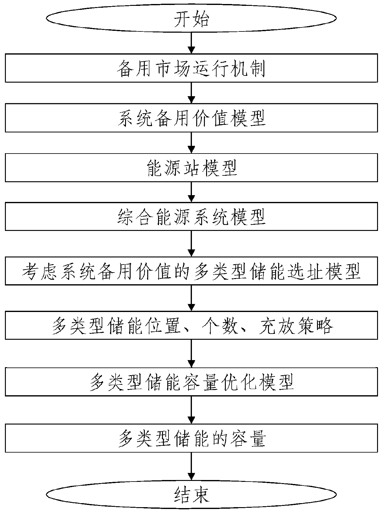
[0035] refer to figure 1 , which is the overall flow chart of the multi-type energy storage configuration method for the integrated energy system proposed in this embodiment. In the specific execution process, it consists of the following steps:

[0036] Step 1. Establish an integrated energy system backup market operation mechanism and establish a system backup value model;

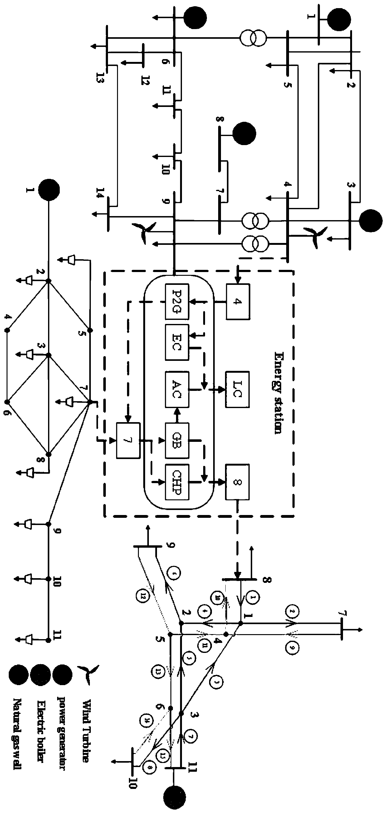
[0037] Step 2. Construct an energy station model for the integrated energy system based on combined cooling, heating, power, and power equipment, and build an integrated energy system model by establishing a heating network model, a gas network model, and a power grid model respectively;

[0038] Step 3. Establish a multi-type energy storage siting model for an integrated energy system considering the system’s reserve value, including establishing multi-type energy storage location objective functions, establishing a dynamic mathematical model for electric energy storage to participate in system operatio...


PUM


Abstract

The invention discloses a multi-type energy storage configuration method for a comprehensive energy system, and the method comprises the steps: building a comprehensive energy system standby market operation mechanism, and building a system standby value model; constructing an energy station model for the comprehensive energy system, and constructing a comprehensive energy system model comprisinga heat supply network model, a gas network model and a power grid model; establishing a comprehensive energy system multi-type energy storage site selection model considering the system standby value;and establishing a comprehensive energy system multi-type energy storage capacity optimization model considering the cycle life. The system operation mode and the system standby value are considered,and the flexibility and the standby capacity of the system can be fully mined. Considering the operation mechanism that the energy station participates in the standby market and establishing a systemstandby value model are beneficial to analyzing the influence of energy station standby on the whole system. Considering the power storage, gas storage and heat storage multi-type energy storage siteselection optimization model and the capacity optimization model is beneficial to obtaining the optimal capacity configuration scheme.

Description


Claims


Application Information

Patent Timeline
Owner NANJING UNIV OF TECH
Learn More