Stably-running optical fiber transceiver for network communication

An optical fiber transceiver, stable operation technology, applied in electromagnetic transceivers and other directions, can solve problems such as affecting equipment communication, affecting communication, equipment operation instability, etc., to achieve the effect of improving practicability and ensuring stable operation

Active Publication Date: 2019-11-22
中邦恒晟有限公司
View PDF3 Cites 0 Cited by
  • Summary
  • Abstract
  • Description
  • Claims
  • Application Information

AI Technical Summary

Problems solved by technology

[0003] When the existing optical fiber transceivers are used, they are usually placed directly on a table or a plane, and the position is not fixed. It is easy to be interfered by external environmental factors and cause the equipment to shift, resulting in poor contact between the optical fiber and the equipment and affecting communication. Not only that , the optical fiber inlets of the existing optical fiber transceivers are generally set on the side of the equipment. Although it is convenient to connect the optical fiber, but at the same time, the position of the optical fiber inlet is exposed. Internally, it affects the communication of the device, resulting in unstable operation of the device, which reduces the practicability of the existing fiber optic transceiver

Method used


Image

  • Stably-running optical fiber transceiver for network communication
  • Stably-running optical fiber transceiver for network communication
  • Stably-running optical fiber transceiver for network communication

Examples


Embodiment Construction

[0025] The present invention is described in further detail now in conjunction with accompanying drawing. These drawings are all simplified schematic diagrams, which only illustrate the basic structure of the present invention in a schematic manner, so they only show the configurations related to the present invention.

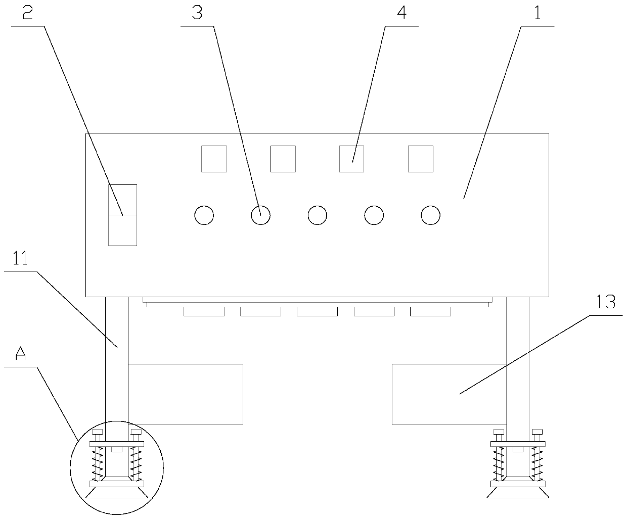
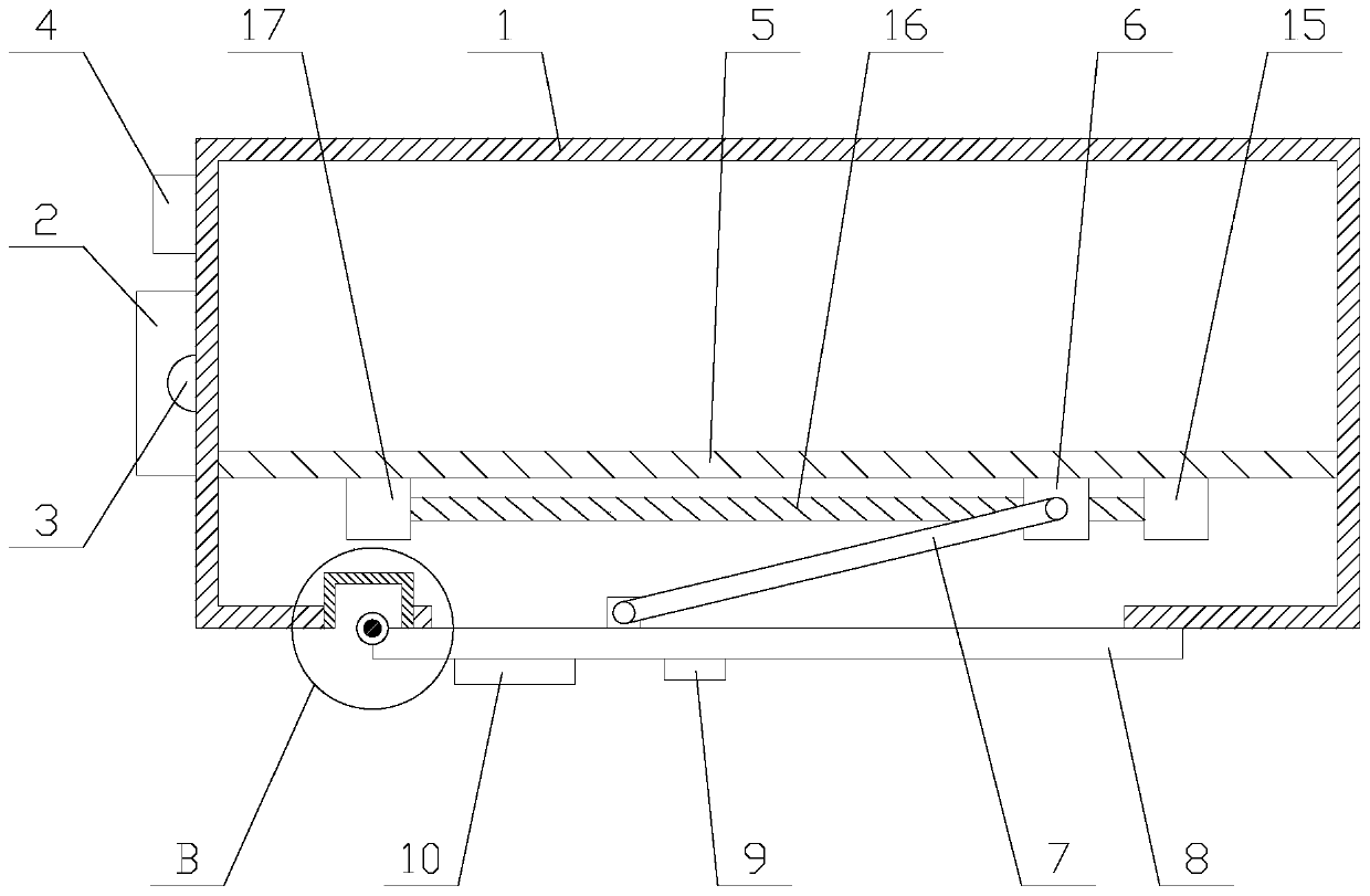
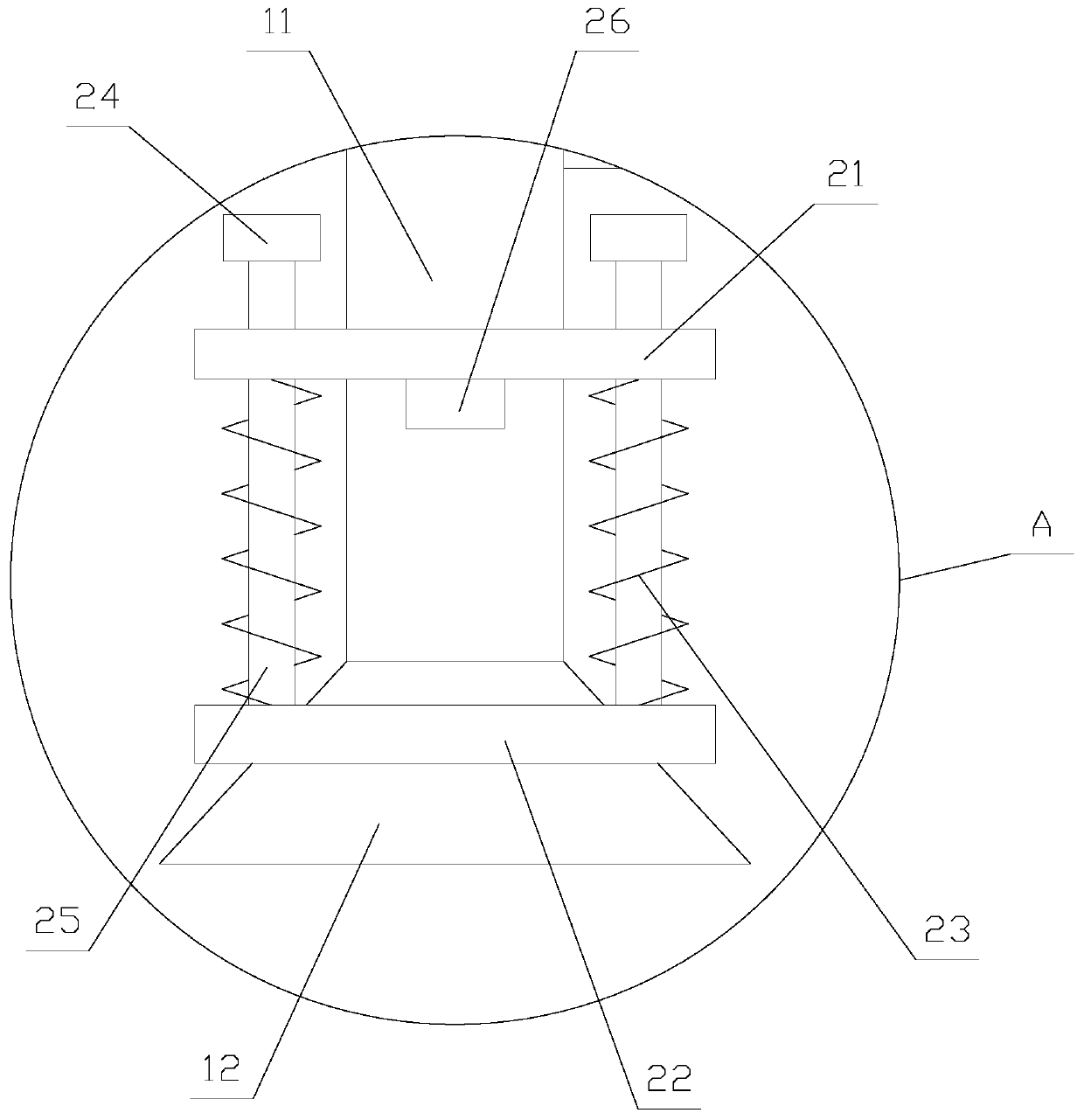
[0026] Such as figure 1 As shown, a fiber optic transceiver with stable operation for network communication includes a housing 1, a wiring mechanism and four supporting mechanisms, and the four supporting mechanisms are respectively arranged at the four corners below the housing 1, and the wiring mechanism is arranged at Below the casing 1, the casing 1 is provided with a switch 2, several indicator lights 3 and several buttons 4, a substrate 5 and a PLC are arranged inside the casing 1, and the indicator lights 3 and the buttons 4 are electrically connected to the PLC;

[0027] PLC, that is, programmable logic controller, which uses a type of programmable me...


PUM


Abstract

The invention relates to a stably-running optical fiber transceiver for network communication. The optical fiber transceiver comprises a shell, a wiring mechanism and four supporting mechanisms, the wiring mechanism comprises a translation assembly, a translation block, a support rod, an opening, a wiring board and a hinge assembly. The supporting mechanism comprises a supporting pipe, a suction cup, a fastening assembly and an air exhaust box. An air exhaust assembly is arranged in the air exhaust box; the air exhaust assembly comprises an air exhaust plate, an air exhaust unit and an air exhaust opening. According to the stably-running optical fiber transceiver for network communication, an external optical fiber can be conveniently accessed through the wiring mechanism; the optical fiber interface is adjusted to the lower part of the shell; in addition, the optical fiber transceiver is fixed on a desktop through the supporting mechanism, the situation that the operation of the equipment is affected by poor contact between the optical fiber and the equipment after the equipment deviates is prevented, the stable operation of the equipment is further guaranteed by fixing the position of the equipment, and the practicability of the optical fiber transceiver is improved.

Description

technical field [0001] The invention relates to the field of optical fiber communication equipment, in particular to an optical fiber transceiver with stable operation for network communication. Background technique [0002] A fiber optic transceiver is an Ethernet transmission media conversion unit that exchanges short-distance twisted-pair electrical signals with long-distance optical signals. It is also called a fiber converter in many places. Products are generally used in actual network environments where Ethernet cables cannot be covered and optical fibers must be used to extend the transmission distance, and are usually positioned in broadband metropolitan area network and access layer applications, such as: high-definition video image transmission for monitoring security engineering, and at the same time Helping connect the last mile of fiber to the metro and beyond has also played a huge role. [0003] When the existing optical fiber transceivers are used, they are...

Claims


Application Information

Patent Timeline
IPC IPC(8): H04B10/40
CPCH04B10/40
Inventor 包宇峰
Owner 中邦恒晟有限公司
Why Eureka
Try Eureka