
Automatic lifting and locking device and method for offshore floating platform

A floating platform, automatic lifting technology, applied in floating buildings, water conservancy projects, artificial islands, etc., can solve the danger of workers and equipment, failure of lifting and locking devices, increase in system complexity, energy consumption failure rate and construction, Maintenance costs and other issues, to achieve the effect of reducing construction and operating costs, no code errors and human errors

Active Publication Date: 2019-11-22
INST OF ELECTRICAL ENG CHINESE ACAD OF SCI
View PDF14 Cites 11 Cited by
  • Summary
  • Abstract
  • Description
  • Claims
  • Application Information

AI Technical Summary

Problems solved by technology

Lifting and locking devices not only increase the complexity of the system, energy consumption, failure rate, and construction and maintenance costs, but also when the sensor is interfered by external noise signals or the sensor itself is damaged, or the computer's operating system and control software have codes running Errors, as well as power failure, personnel not in place, personnel misoperation, etc., send wrong operation instructions to the lifting and locking device, the lifting and locking device will fail, malfunction, stop, over-lift or over-fall, and give the floating platform cause danger, damage or even catastrophic consequences to the crew and equipment carried on board

Method used


Image

  • Automatic lifting and locking device and method for offshore floating platform
  • Automatic lifting and locking device and method for offshore floating platform
  • Automatic lifting and locking device and method for offshore floating platform

Examples


Embodiment Construction

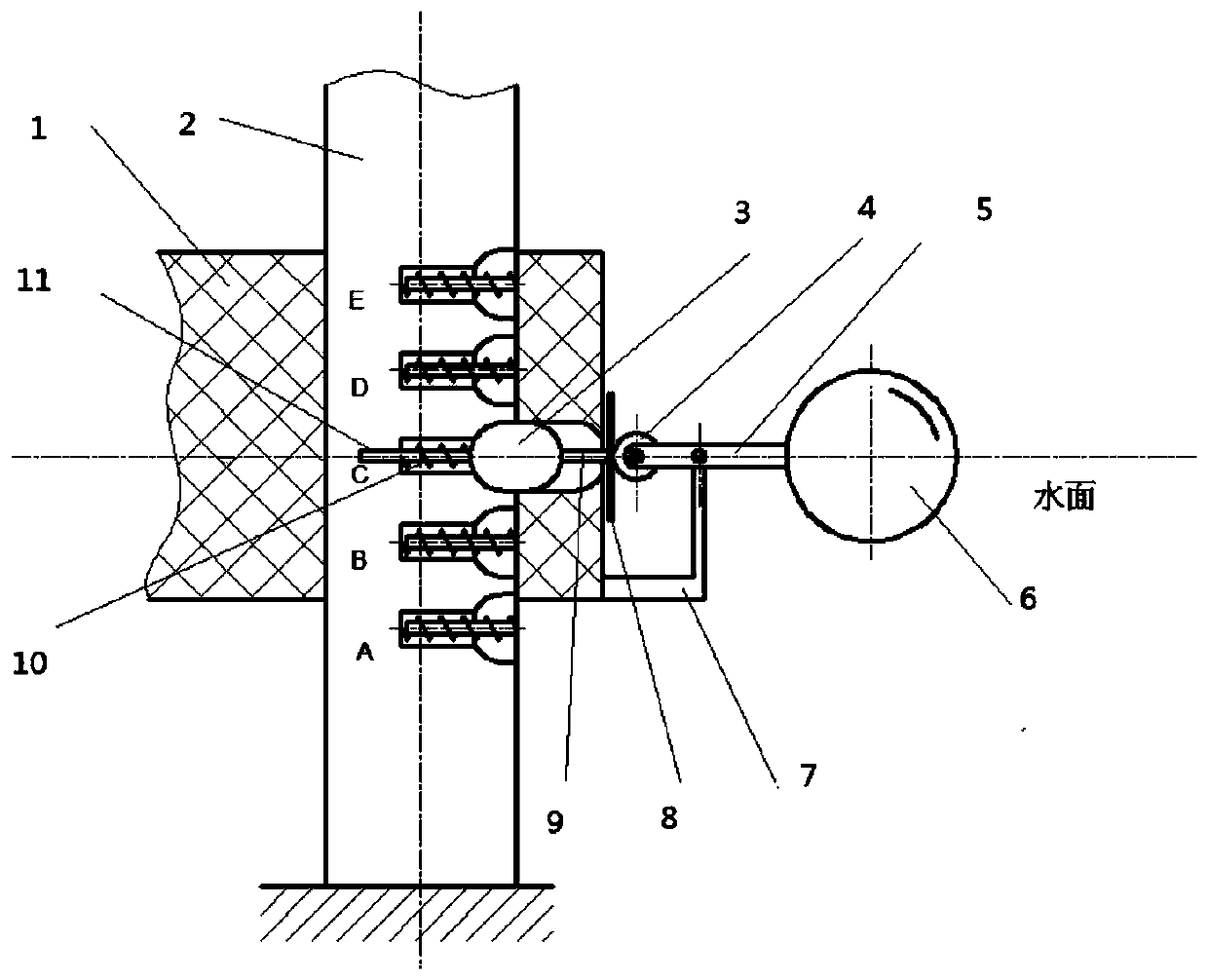
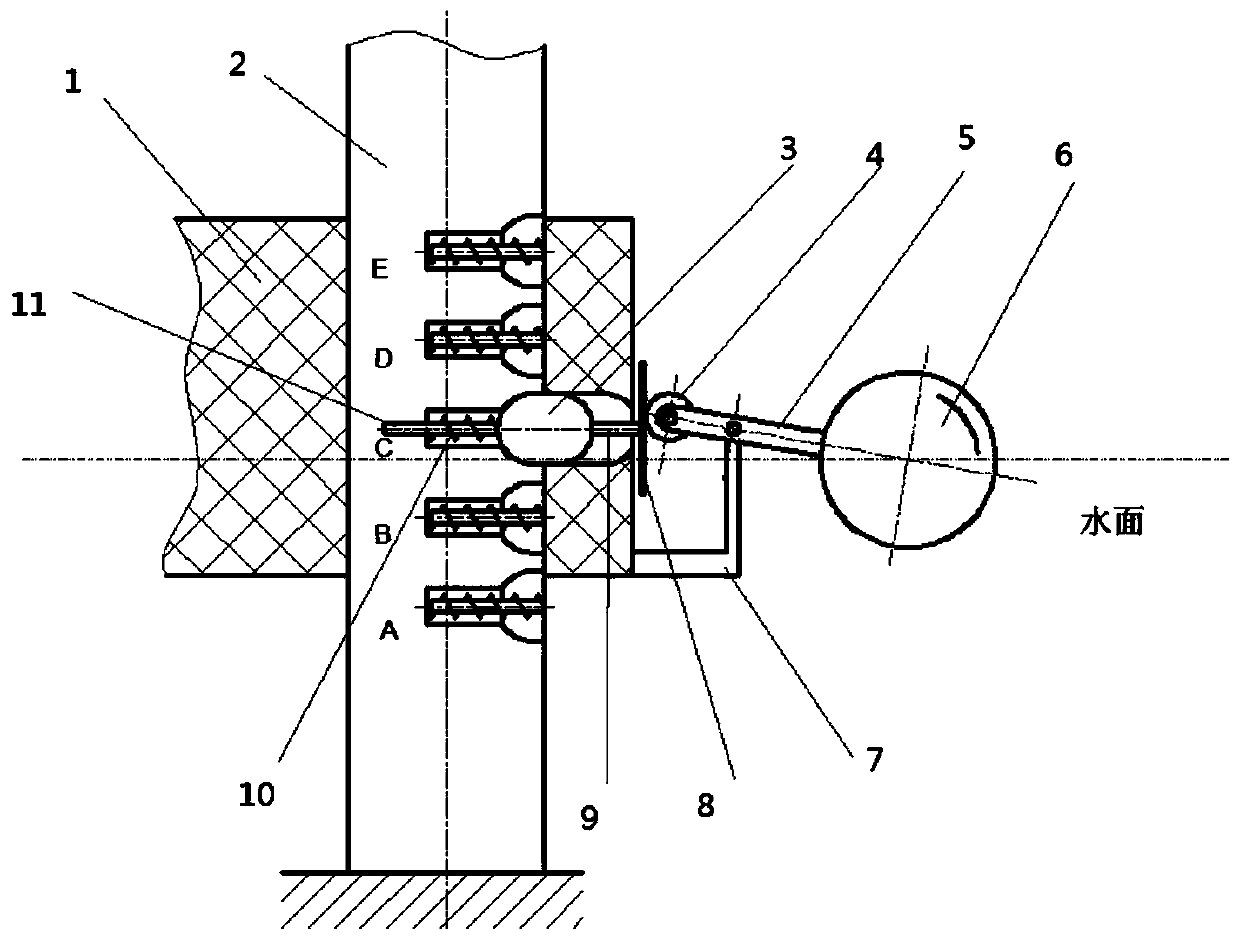
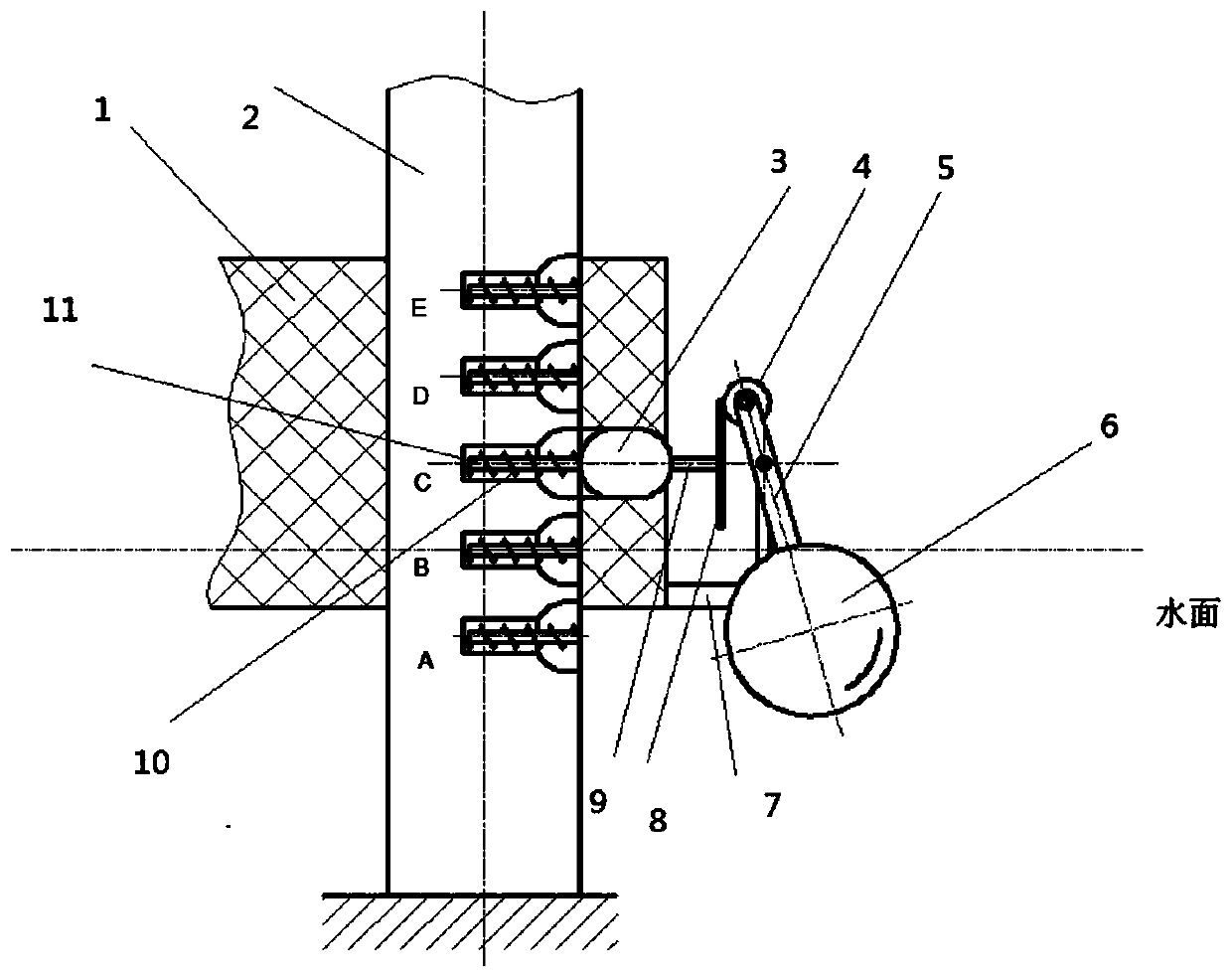
[0031]The present invention is mainly aimed at those working floating platforms that are operated on the sea surface, and need to rely on support columns anchored on the seabed to bear natural force and engineering force, keep the working position unchanged, and rise and fall with the tide. The present invention designs and installs a mechanical automatic unlocking and locking mechanism between the floating platform and the support column, which consists of sliding pins, push rods, push plates, floating balls, swing rods, rollers, connecting frames, compression springs and Rod composition. The sliding pin is located in the horizontal hole of the floating platform and the supporting column, and can move horizontally. When the floating platform and the floating ball are in balance, part of the sliding pin is located in the horizontal hole of the floating platform, and the other part is located in the horizontal hole of the supporting column. The floating platform is in the horizo...


PUM


Abstract

The invention relates to an automatic lifting and locking device and method for an offshore floating platform. Ascending and descending of the floating platform depends on the combined action of buoyancy and gravity of the floating platform, and an automatic unlocking and locking mechanism is arranged between the floating platform and a supporting column, so it is guaranteed that the floating platform fluctuates along with tides, and it is also guaranteed that the floating platform can bear transverse and longitudinal stress. The automatic unlocking and locking mechanism is composed of a sliding pin, a push rod, a push disc, a floating ball, a swing rod, an idler wheel, a floating platform and a supporting column, wherein the push rod and the push disc are connected with the sliding pin; the swing rod and the idler wheel are connected with the floating ball; horizontal holes are arranged in the floating platform and the supporting column; the idler wheel is pressed on the push disc; the swing rod is fixed to the floating platform through a connecting frame; compression springs and ejector rods are arranged in a plurality of horizontal holes in the supporting column; and the ejectorrods abut against the sliding pin. By means of the automatic lifting and locking device, the floating platform can ascend and descend along with changes of the sea level along with tides, meanwhile,the floating platform can be automatically locked and limited, and it is guaranteed that the floating platform bears natural force and engineering force. Compared with the prior art, the device is simple in structure, safe, reliable and free of energy consumption.

Description

technical field [0001] The invention relates to a device and method for automatically lifting and locking an offshore floating platform with the tide, and belongs to the field of facility design, construction and engineering of the offshore floating working platform. Background technique [0002] Some working platforms floating on the sea, such as temporary docks, floating artificial islands, temporary airports on the sea, floating fences for aquaculture, etc., need to be moored on the water all the time to work, and the platform must bear horizontal and vertical pressure from waves, storms, ocean currents, etc. under working conditions. The natural force in the same direction and the engineering force generated by the equipped equipment must maintain a fixed working position, and the support column needs to sink to the seabed to take root and fix it; at the same time, due to the tidal phenomenon of seawater, the seawater depth of the floating platform is one day There will be...

Claims


Application Information

Patent Timeline
Patent Type & Authority Applications(China)
IPC IPC(8): B63B35/44E02B17/08
CPCB63B35/44E02B17/08
Inventor 王厚生
Owner INST OF ELECTRICAL ENG CHINESE ACAD OF SCI
Learn More