
Bicycle bell with brake handle

A bicycle and brake lever technology, which is applied to bicycle accessories, bicycle brakes, audio signals, etc., can solve the problems of unsafe, unable to grasp the handlebar normally, and achieve the effect of eliminating potential safety hazards.

Active Publication Date: 2019-11-22
武成阁
View PDF5 Cites 1 Cited by
  • Summary
  • Abstract
  • Description
  • Claims
  • Application Information

AI Technical Summary

Problems solved by technology

[0002] The bicycle bell is an important part to ensure the safety of bicycle driving. The traditional bicycle bell adopts the hand dial type to sound, mainly including the bell bowl. The side of the bell bowl is equipped with a lever. The bell hammer, when the lever is moved, will drive the bell hammer inside the bell bowl to hit the inner wall of the bell bowl, and the bell will sound. When holding the handlebar, if there are obstacles or bumps on the road, accidents may occur, which is very unsafe

Method used


Image

  • Bicycle bell with brake handle
  • Bicycle bell with brake handle
  • Bicycle bell with brake handle

Examples


Embodiment 1

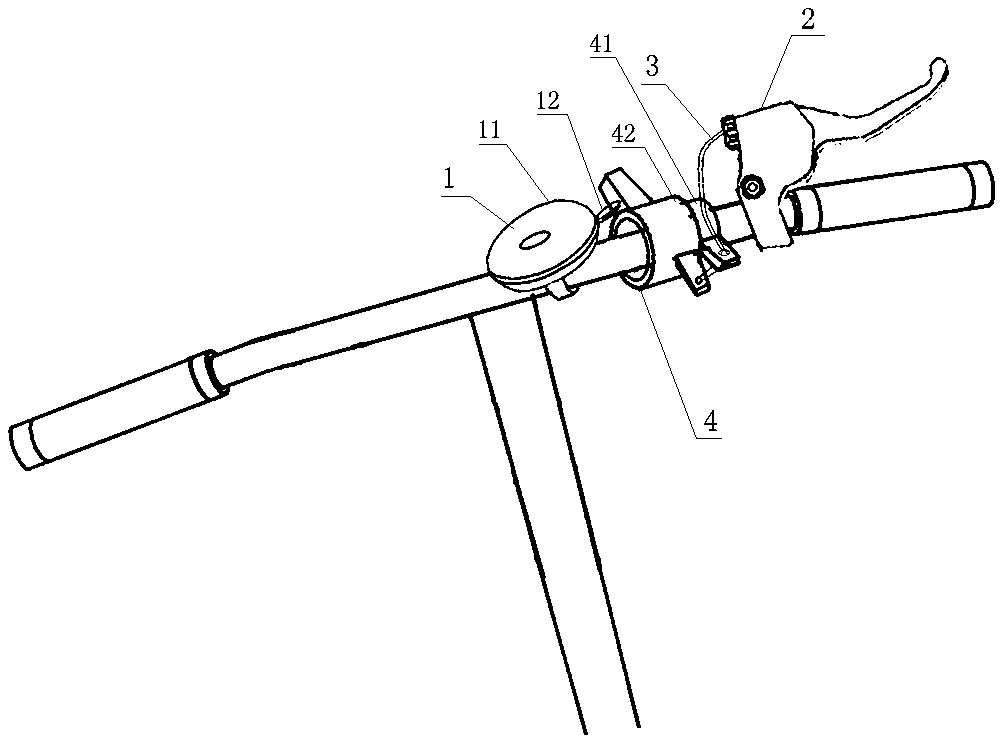
[0020] Such as figure 1 , 2 As shown, a bicycle bell with a brake handle includes a bicycle bell 1, a brake handle 2, and a pull wire 3. The bicycle bell 1 and the brake handle 2 are installed on the handlebar. The bicycle bell 1 includes a bell bowl 11 and a lever 12, and also includes a dial The bell structure 4, the dial bell structure 4 is installed on the handlebar, the brake handle 2 is connected with the dial bell structure 4 through the stay wire 3, the dial bell structure 4 is connected with the lever 12 of the car bell 1, and the brake handle 2 is kneaded and loosened. Release, and the pull wire 3 drives the bell structure 4 to work, and the lever 12 is moved to make the bell 1 ring.

[0021] The brake handle is an important part to ensure the safety of bicycle driving. There are usually two traditional bicycle brake handles, which respectively control the front brake and the rear brake. Brake braking, the use probability of the front brake is very low, so the fron...

Embodiment 2

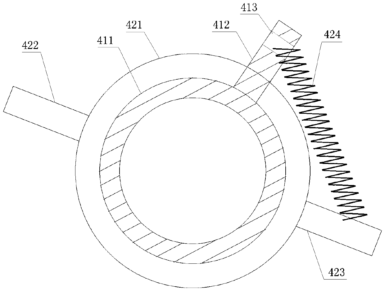
[0024] Such as figure 2 , 3 As shown, the dialing bell structure 4 includes a fixing part 41 and a ringing part 42. The fixing part 41 includes a cylinder 411, and the cylinder 411 is provided with a short arm 412. One end of the short arm is connected to the cylinder, and the other end is provided with a pull wire The hole 413, the cylindrical body 411 is installed on the handlebar, and the bell part 42 is installed on the fixing part 41.

[0025] The pull wire 3 passes through the pull wire hole 413 and is connected with the bell part 42 .

Embodiment 3

[0027] The cylinder body 411 is divided into two parts longitudinally, and is fitted on the handlebar through a connecting piece, and the connecting piece is a screw or a bolt.


PUM


Abstract

The invention discloses a bicycle bell with a brake handle. The bicycle bell comprises a bell body, a brake handle and a pull wire, the bell body and the brake handle are installed on a handlebar, thebell body comprises a bell bowl and a poking rod, the bicycle bell also comprises a bell poking structure, the bell poking structure is installed on the handlebar, the brake handle is connected withthe bell poking structure through the pull wire, the bell poking structure is connected with the poking rod of the bell body, and the pull wire drives the bell poking structure to work and poke the poking rod to ring. According to the invention, the vehicle front brake handle with low use efficiency is utilized; the bell is controlled by the pull wire of the brake handle; and the bicycle bell is controlled to make a sound through holding and releasing of the brake handle, so the bicycle bell is more convenient and safer to control, the palm does not need to leave the brake handle at all duringbell poking, the situation that one hand of a rider partially or completely leaves the handlebar for bell poking is avoided, and potential safety hazards caused by the fact that the rider loses balance when holding the handlebar with one hand in the riding process are eliminated.

Description

technical field [0001] The invention relates to a bicycle safety device, in particular to a brake handle bicycle bell. Background technique [0002] The bicycle bell is an important part to ensure the safety of bicycle driving. The traditional bicycle bell adopts the hand dial type to sound, mainly including the bell bowl. The side of the bell bowl is equipped with a lever. The bell hammer, when the lever is moved, will drive the bell hammer inside the bell bowl to hit the inner wall of the bell bowl, and the bell will sound. When holding the handlebar, if there are obstacles or bumps on the road, accidents may occur, which is very unsafe. Contents of the invention [0003] The purpose of the present invention is to overcome the defects in the prior art, and provide a bicycle bell that can not only firmly grasp the handlebar, but also dial in time. [0004] In order to achieve the above object, the technical solution adopted in the present invention is: a bicycle bell wi...

Claims


Application Information

Patent Timeline
Patent Type & Authority Applications(China)
IPC IPC(8): B62J3/00B62L3/02
CPCB62J3/00B62L3/026B62J3/04
Inventor 武成阁
Owner 武成阁
Learn More