
Lumbar vertebra interbody fusion cage and application thereof

An intervertebral fusion device and fusion device technology, applied in the medical field, can solve the problems of high cancellous bone content, fatigue damage, stress shielding, etc., and achieve the effects of good fatigue resistance, avoiding stress shielding, and preventing fatigue damage

Inactive Publication Date: 2019-11-22
THE AFFILIATED HOSPITAL OF PUTIAN UNIV (THE SECOND HOSPITAL OF PUTIAN CITY)
View PDF0 Cites 2 Cited by
  • Summary
  • Abstract
  • Description
  • Claims
  • Application Information

AI Technical Summary

Problems solved by technology

Although traditional surgical methods can achieve relatively high fusion rates, there are still some problems: complications caused by infection, nerve damage, blood loss and graft loosening
However, due to the limited volume of human cortical bone, the posterior intervertebral fusions currently used in China, such as three-sided cortical intervertebral fusions, all contain more cancellous bone components, which are difficult to meet the mechanical strength of supporting the anterior column
[0005] To sum up, the intervertebral fusion devices currently used clinically have: 1. High-strength metal intervertebral fusion devices are prone to stress shielding problems, which is not conducive to osteogenesis, while low-strength metal intervertebral fusion devices The support strength is insufficient, and fatigue damage is prone to occur; 2. The carbon fiber intervertebral fusion is prone to debris under repeated force, leading to the occurrence of aseptic inflammation; 3. The autologous bone contained in the intervertebral fusion contains cancellous High bone content, resulting in insufficient mechanical strength of the intervertebral cage

Method used


Image

  • Lumbar vertebra interbody fusion cage and application thereof
  • Lumbar vertebra interbody fusion cage and application thereof
  • Lumbar vertebra interbody fusion cage and application thereof

Examples


Embodiment Construction

[0022] The following will clearly and completely describe the technical solutions in the embodiments of the present invention with reference to the accompanying drawings in the embodiments of the present invention. Obviously, the described embodiments are only some, not all, embodiments of the present invention. Based on the embodiments of the present invention, all other embodiments obtained by persons of ordinary skill in the art without creative efforts fall within the protection scope of the present invention.

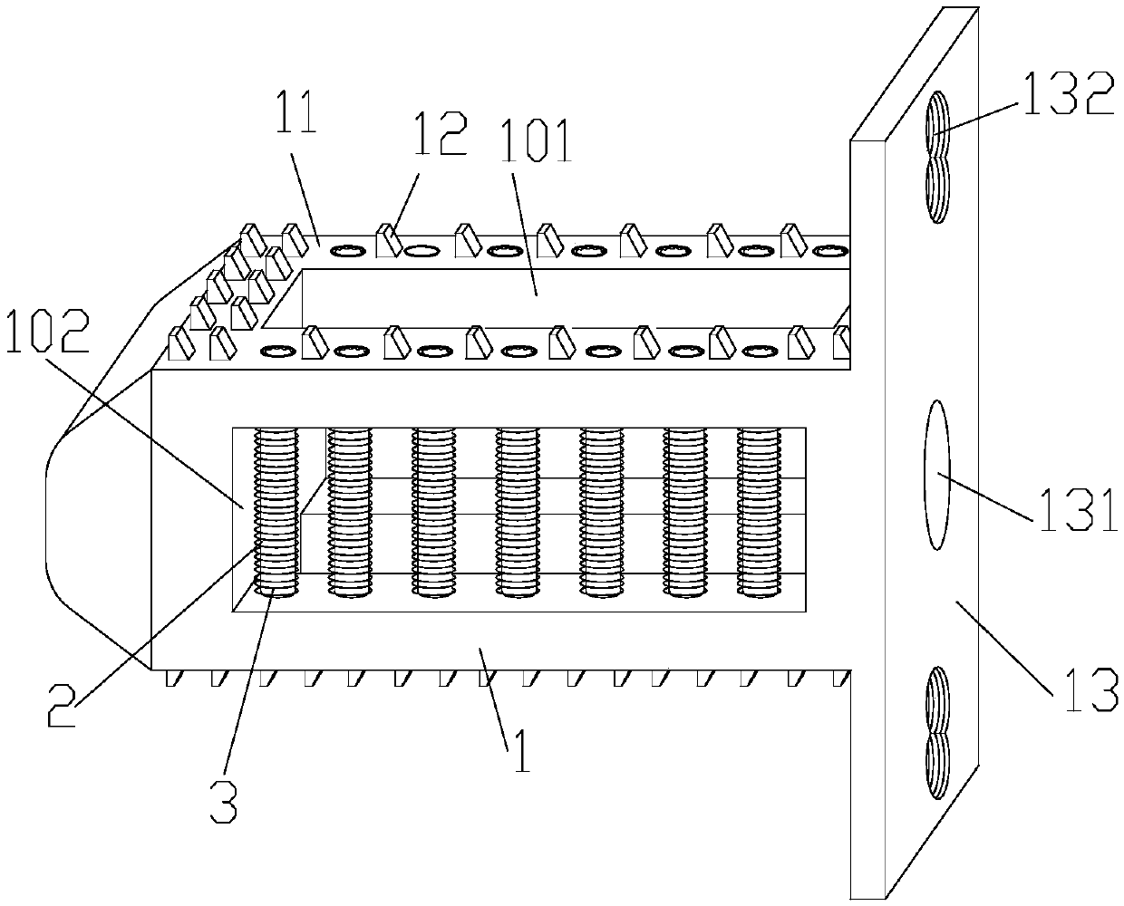
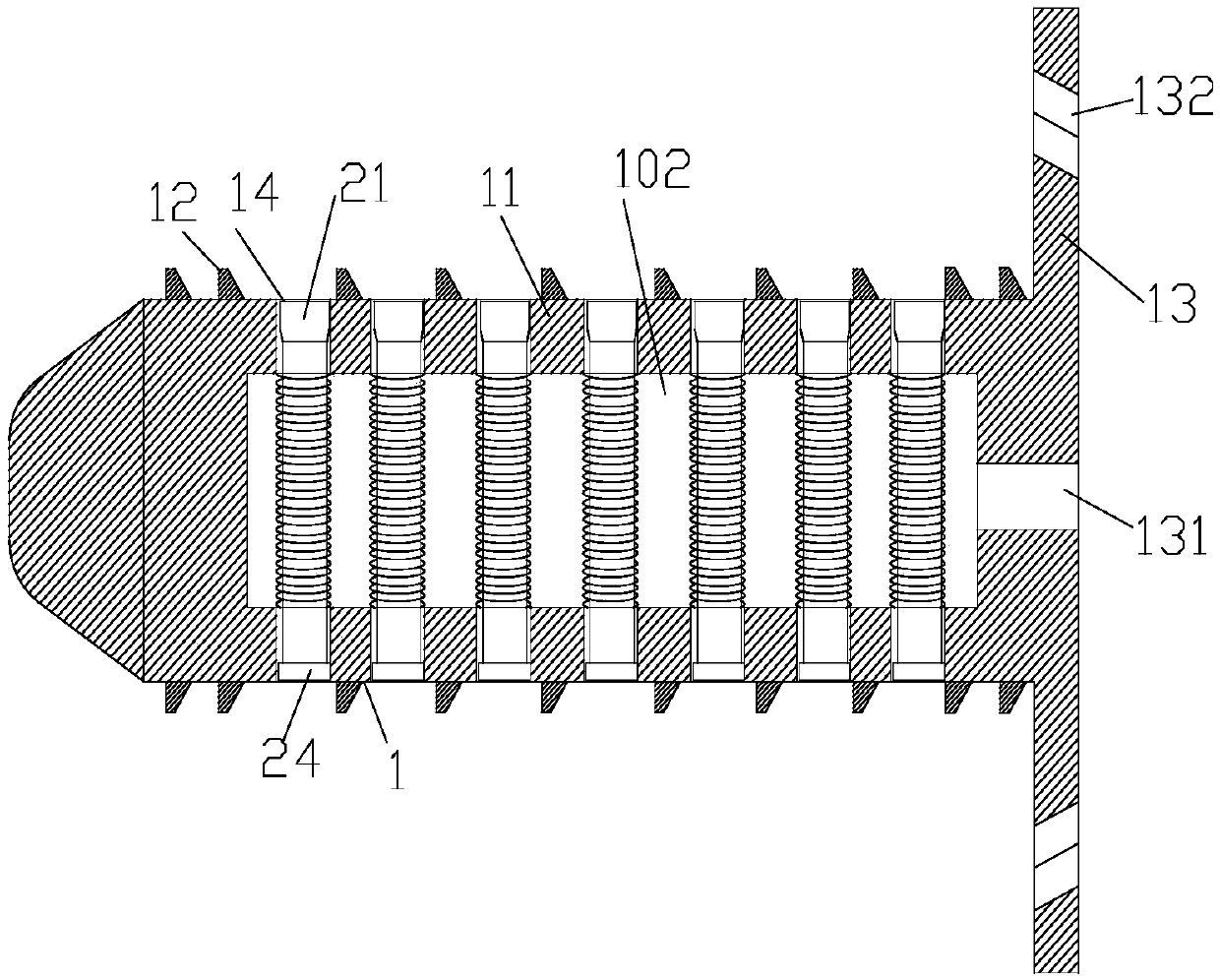
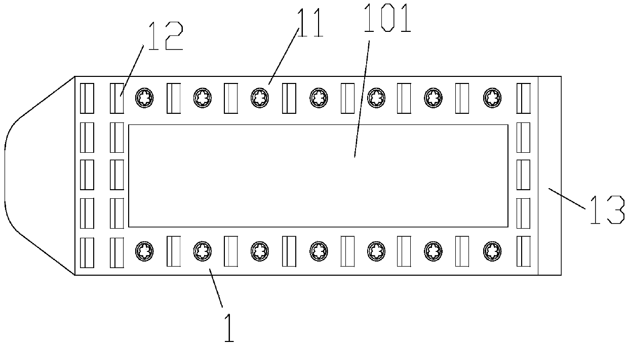
[0023] refer to Figure 1-6 As shown, a lumbar intervertebral fusion device includes a fusion device body 1, the left end of the fusion device body 1 is a tapered wedge-shaped implant end, the right end of the fusion device body 1 is provided with a tail plate 13, and the fusion device body 1 There is a through central bone graft hole 101 on the top, and a through side hole is opened on the facade of the cage. The central bone graft hole 101 and the side hole 102 d...


PUM


Abstract

The invention discloses a lumbar vertebra interbody fusion cage and application thereof. The lumbar vertebra interbody fusion cage comprises a fusion cage body, the left end of the fusion cage body isa tapered wedge-shaped implant end, a tail plate is arranged on the right end part of the fusion cage body, a penetrating central bone grafting hole is formed in the top of the fusion cage body, a penetrating side hole is formed in the vertical surface of the fusion cage, the central bone grafting hole and the side hole divide the fusion cage body into four cross beams, compression energy dissipating devices are fixed between the cross beams, anti-skid protrusions are arranged on the top surface and the bottom surface of the fusion cage body, 8-shaped screw holes are formed in the upper end and the lower end of the tail plate, and the middle of the tail plate is provided with a repair bone grafting hole penetrating through the central bone grafting hole. According to the interbody fusioncage, a strong-column and weak-beam structure is adopted, a high-strength interbody body fusion cage made of metal materials does not need to be used, and an elastic module of the high-strength metalinterbody body fusion cage can be achieved; the anti-fatigue rupture performance of the interbody fusion cage is better; the interbody body fusion cage is combined with a vertebra screw to limit the axial torsional movement of the lumbar intervertebral disc, and thus the fracture of the interbody fusion cage is avoided.

Description

technical field [0001] The invention relates to the field of medical technology, in particular to a lumbar intervertebral fusion device and its application. Background technique [0002] In 1944, Briggs and Miligan first invented the posterior approach of interbody fusion. The classic surgical method is to implant bone fragments or autogenous iliac crest into the intervertebral body after decompression from the posterior approach in order to achieve stable fusion. Cloward used this technique to achieve an 85% long-term fusion rate in 321 patients. Although traditional surgical methods can achieve relatively high fusion rates, there are also some problems: complications caused by infection, nerve damage, blood loss, and graft loosening. A successful posterior intervertebral fusion requires adequate axial support of the anterior column while avoiding implant subsidence and damage. The traditional intervertebral implantation of autologous or allogeneic cancellous bone obviou...

Claims


Application Information

Patent Timeline
Patent Type & Authority Applications(China)
IPC IPC(8): A61F2/44
CPCA61F2/4455
Inventor 陈宣煌郑锋吴长福张国栋
Owner THE AFFILIATED HOSPITAL OF PUTIAN UNIV (THE SECOND HOSPITAL OF PUTIAN CITY)
Learn More