
Heat dissipation electrical cabinet with electric automatic control function

A technology of electrical automation and electrical cabinets, applied in the field of electrical cabinets, can solve the problems of affecting the heat dissipation of electrical cabinets, damage of electrical components of electrical cabinets, and large dust in filter screens, and achieve the effect of avoiding damage to electrical components

Active Publication Date: 2019-11-19
NORTHEAST AGRICULTURAL UNIVERSITY
View PDF6 Cites 16 Cited by
  • Summary
  • Abstract
  • Description
  • Claims
  • Application Information

AI Technical Summary

Problems solved by technology

[0004] The technical problem to be solved by the present invention is to provide a heat dissipation electric cabinet controlled by electric automation, so as to solve the problem that a large amount of dust will accumulate on the filter screen of the electric cabinet in the prior art, which will affect the heat dissipation of the electric cabinet and easily cause the electrical components in the electric cabinet to be damaged. Damaged technical issues

Method used


Image

  • Heat dissipation electrical cabinet with electric automatic control function
  • Heat dissipation electrical cabinet with electric automatic control function
  • Heat dissipation electrical cabinet with electric automatic control function

Examples


Embodiment Construction

[0026] In order to make the object, technical solution and advantages of the present invention clearer, the present invention will be further described in detail below in conjunction with the accompanying drawings and embodiments. It should be understood that the specific embodiments described here are only used to explain the present invention, not to limit the present invention.

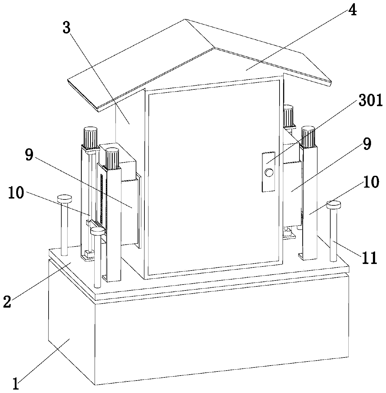
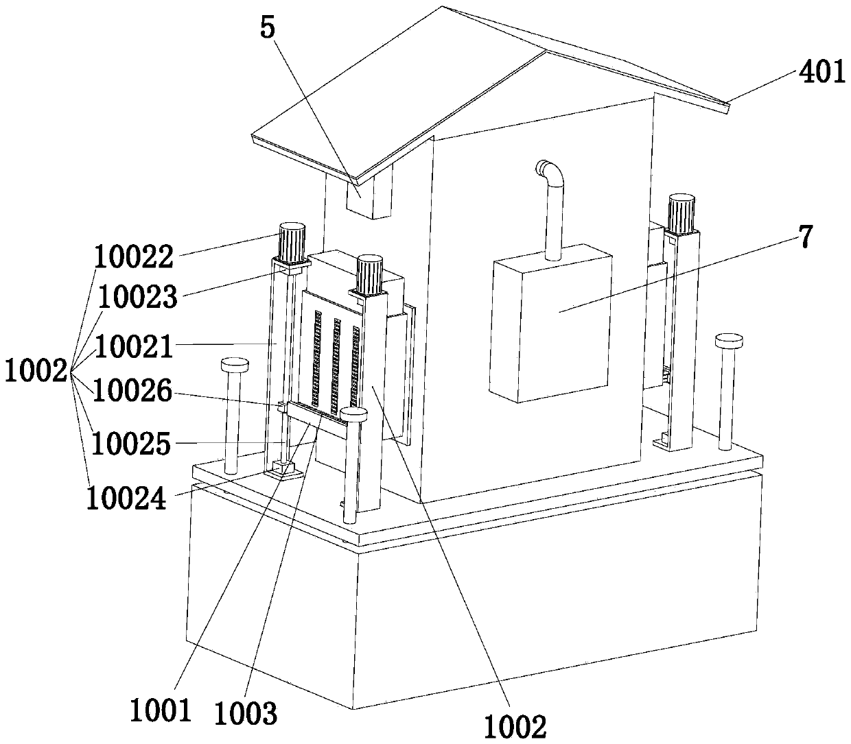
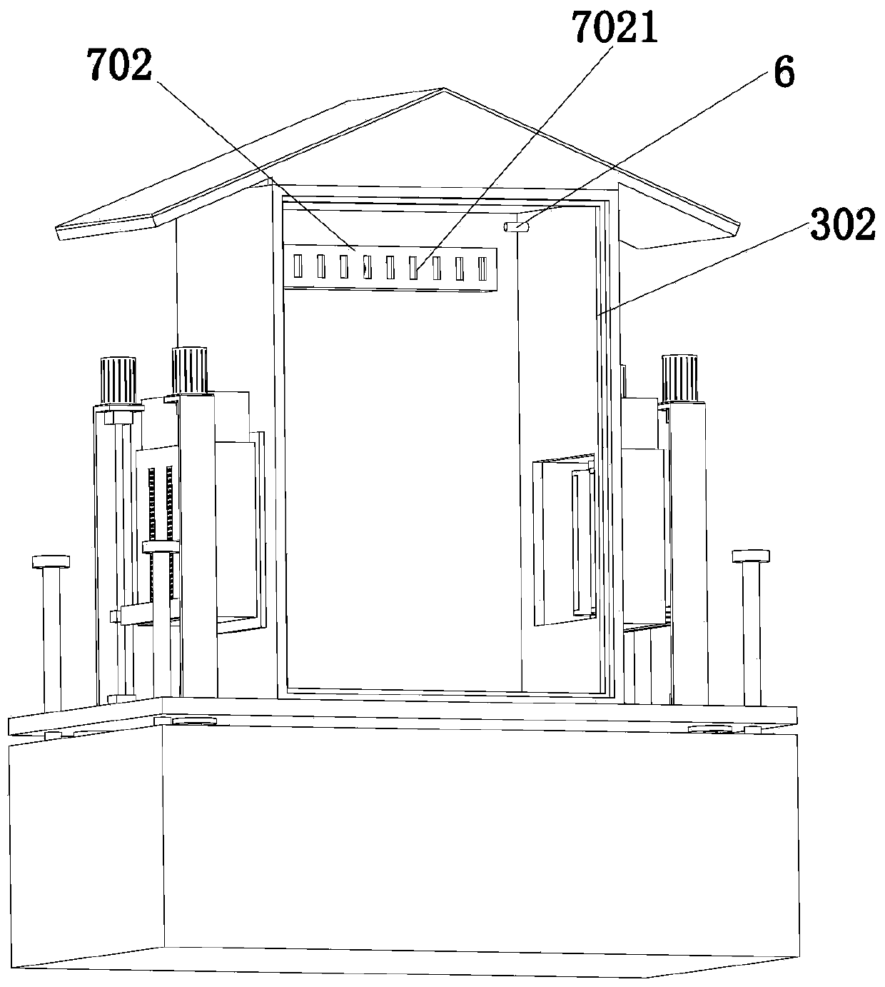
[0027] refer to Figure 1 to Figure 7It can be seen that the present invention provides a heat dissipation electrical cabinet controlled by electrical automation, including a bottom box 1, a lifting plate 2, an electrical cabinet body 3, a herringbone top 4, a controller 5, a temperature sensor 6, a refrigeration assembly 7, and a lifting assembly 8. Two heat dissipation components 9, two dust removal components 10 and four limiting columns 11, the bottom box 1 is set on the ground, and the four limiting columns 11 are distributed on the top of the bottom box 1 in a rectangular shape , the lifting...


PUM


Abstract

The invention discloses a heat dissipation electrical cabinet with an electric automatic control function and belongs to the technical field of electrical cabinets. The heat dissipation electrical cabinet comprises a bottom box, a lifting plate, an electrical cabinet body, a herringbone top, a controller, a temperature sensor, a refrigerating assembly, a lifting assembly, two heat dissipation assemblies, two dust removal assemblies and four limiting columns; the bottom box is arranged on the ground; the four limiting columns are distributed at the top of the bottom box rectangularly; the lifting plate is slidingly mounted on the four limiting columns; the electric cabinet body is arranged on the lifting plate; the controller is arranged on the outer wall of the electric cabinet body; the temperature sensor is arranged on the inner wall of the electric cabinet body; the refrigerating assembly is installed on the outer wall of the electric cabinet body; the lifting assembly is installedin the bottom box; the two heat dissipation assemblies are symmetrically arranged on the outer wall of the electric cabinet body; and the two dust removal assemblies are symmetrically arranged on thelifting plate. According to an electrical cabinet in the prior art, a large amount of dust will be accumulated on the filter screen of the electrical cabinet, and as a result, the heat dissipation ofthe electrical cabinet will be affected, and the electrical components in the electrical cabinet is likely to be damaged. However, with the heat dissipation electrical cabinet with the electric automatic control function of the invention adopted, the problem in the prior art can be solved.

Description

technical field [0001] The invention relates to the technical field of electrical cabinets, in particular to a heat dissipation electrical cabinet controlled by electrical automation. Background technique [0002] The electrical cabinet is a cabinet made of steel to protect the normal operation of components. The materials for making electrical cabinets are generally divided into two types: hot-rolled steel plate and cold-rolled steel plate. Compared with hot-rolled steel sheets, cold-rolled steel sheets are softer and more suitable for the production of electrical cabinets. Electrical cabinets are widely used mainly in chemical industry, environmental protection industry, power system, metallurgical system, industry, nuclear power industry, fire safety monitoring, transportation industry and so on. [0003] The existing patent number CN108808514A discloses a heat-dissipating electrical cabinet controlled by electrical automation, including an electrical cabinet body, an u...

Claims


Application Information

Patent Timeline
Patent Type & Authority Applications(China)
IPC IPC(8): H02B1/30H02B1/56H02B1/28B08B1/00
CPCB08B1/00H02B1/28H02B1/30H02B1/565
Inventor 魏东辉房俊龙刘桂林李天舒吴茜
Owner NORTHEAST AGRICULTURAL UNIVERSITY
Learn More