Electronic padlock

An electronic and lock body technology, applied in padlocks, electric alarm locks, building locks, etc., can solve the problems of increasing the size of the lock body, large installation work, and functional interruption, etc., to reduce space, compact design, and reduce assembly costs Effect

Active Publication Date: 2019-11-19
ABUS AUGUST BREMICKER SOEHNE AG
View PDF5 Cites 0 Cited by
  • Summary
  • Abstract
  • Description
  • Claims
  • Application Information

AI Technical Summary

Problems solved by technology

Vibrations can be transmitted to the components of the electrical unit, or cause relative movements of the components of the electrical unit, which can affect the high performance of the U-lock or even lead to a complete functional interruption
Another problem is the space required in the lock body for fixing parts, which increases the size of the lock body
In addition, the fixing of the individual parts of the electrical unit requires considerable installation work, which increases the manufacturing costs of such padlocks

Method used


Image

  • Electronic padlock
  • Electronic padlock
  • Electronic padlock

Examples


Embodiment Construction

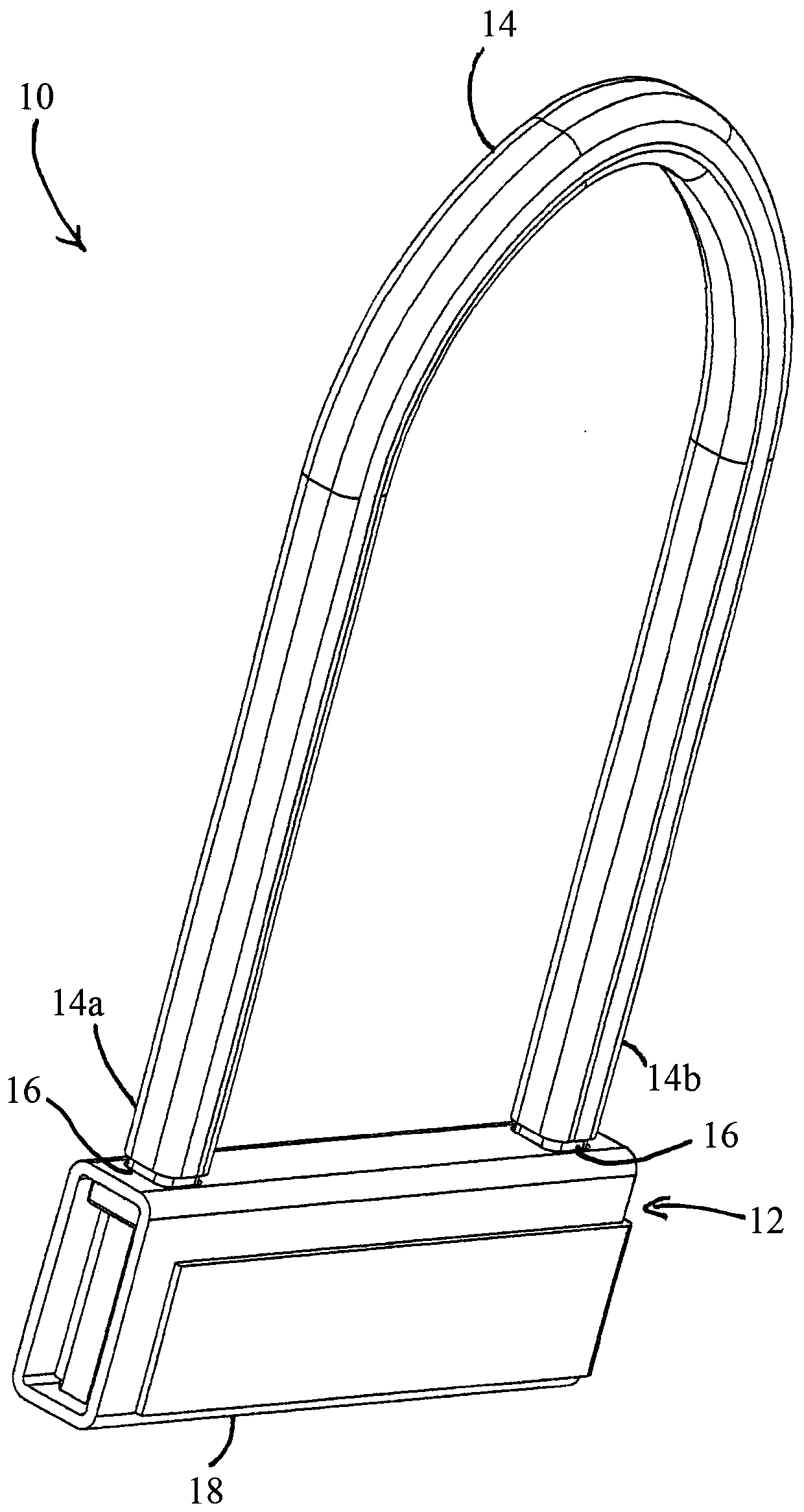
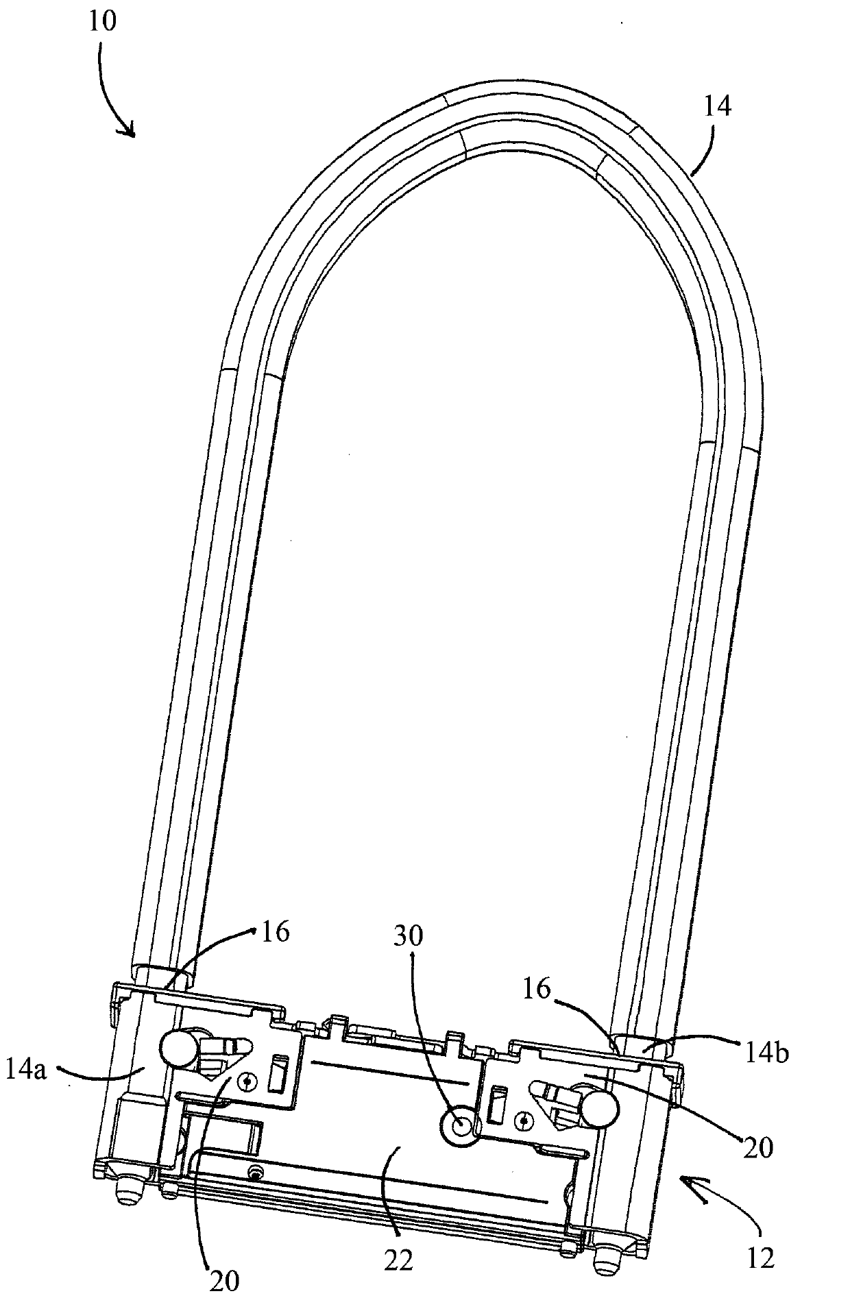
[0056] figure 1 and figure 2 A perspective view of an embodiment of an electronic padlock 10 according to the present application is shown in each case. Padlock 10 includes a lock body 12 and a lock bow 14 . In the exemplary embodiment shown herein, the lock bow 14 is designed as U-shaped, and has a first end 14a and a second end 14b, and the first end 14a and the second end 14b are inserted into the lock hole 16 of the lock body 12 . Lock body 12 comprises shell 18 (as figure 2 shown removed), locking mechanism 20 and inner housing 22. The locking mechanism 20 and inner housing 22 are disposed within the outer housing 18 and are thereby protected from damage. The housing 18 is made of metal and may additionally be surrounded by a plastic sheath (not shown).

[0057] figure 1 and figure 2 The lock bow 14 is shown in the closed position, wherein the first end 14 a and the second end 14 b of the lock bow 14 are locked in the lock body 12 by the locking mechanism 20 . ...


PUM


Abstract

An electronic padlock for a two-wheeled vehicle includes a lock body and a lock bow movable relative to the lock body between a closed position and an open position, where the lock body includes a housing, a locking mechanism, and an electrical unit. An elastic molded part comprising a plurality of receiving parts is inserted into the shell in a shape matching manner, and a plurality of componentsof the electrical unit are accommodated in the receiving parts in a shape matching manner.

Description

technical field [0001] The present application relates to an electronic padlock for two-wheeled vehicles. The padlock includes a lock body and a lock bow, the lock bow can move between a closed position and an open position relative to the lock body, the lock body includes a housing, a locking mechanism and an electrical unit, wherein the lock bow can be locked to the closed position by the locking mechanism lock body. Background technique [0002] Such padlocks are known, for example, as U-bow padlocks, which have an approximately U-shaped lock bow. Padlocks of the above-mentioned type can also be designed as folding locks comprising an articulating lever bow with a plurality of rotatably interconnected articulating levers. Padlocks of the above-mentioned type can also be designed as so-called frame locks, in which the swivel bow or swivel bow engages between the spokes of a wheel of a bicycle. In another embodiment, such a padlock is designed as a brake disc lock, which...

Claims


Application Information

Patent Timeline
Patent Type & Authority Applications(China)
IPC IPC(8): E05B67/00E05B47/00E05B45/06
CPCE05B67/00E05B47/0012E05B45/005E05B2047/0094E05B2047/0058E05B2047/0096E05B67/063E05B67/02
Inventor 不公告发明人
Owner ABUS AUGUST BREMICKER SOEHNE AG
Why Eureka
Try Eureka