
An electric pole pole device

The technology of a pole device and an electric pole, which is applied in the field of electric power equipment, can solve the problems of high labor intensity, unstable construction of poles, and difficulty in increasing poles and poles.

Active Publication Date: 2020-10-27
ZHANGQIU POWER SUPPLY CO OF STATE GRID SHANDONG ELECTRIC POWER CO +1
View PDF5 Cites 3 Cited by
  • Summary
  • Abstract
  • Description
  • Claims
  • Application Information

AI Technical Summary

Problems solved by technology

Manual cooperation with crane construction, manual cooperation with crane construction, excavation of rod pits and filling and compaction are also done manually, which is labor-intensive
The participation of the crane has greatly reduced the labor intensity of the construction workers, but only one rope sleeve for the crane to lift the pole bears the weight of the entire pole, and most of the construction workers are within the distance of the pole. If the rope cover of the pole falls off or is broken, the personal injury to the construction personnel is unimaginable. The process of erecting the pole in this way is unstable, and the safety risk is relatively large; in addition, for some rugged areas, the crane cannot drive into the construction site. Further increases the difficulty of the pole pole, for this reason, we propose a pole pole device

Method used


Image

  • An electric pole pole device
  • An electric pole pole device
  • An electric pole pole device

Examples


Embodiment Construction

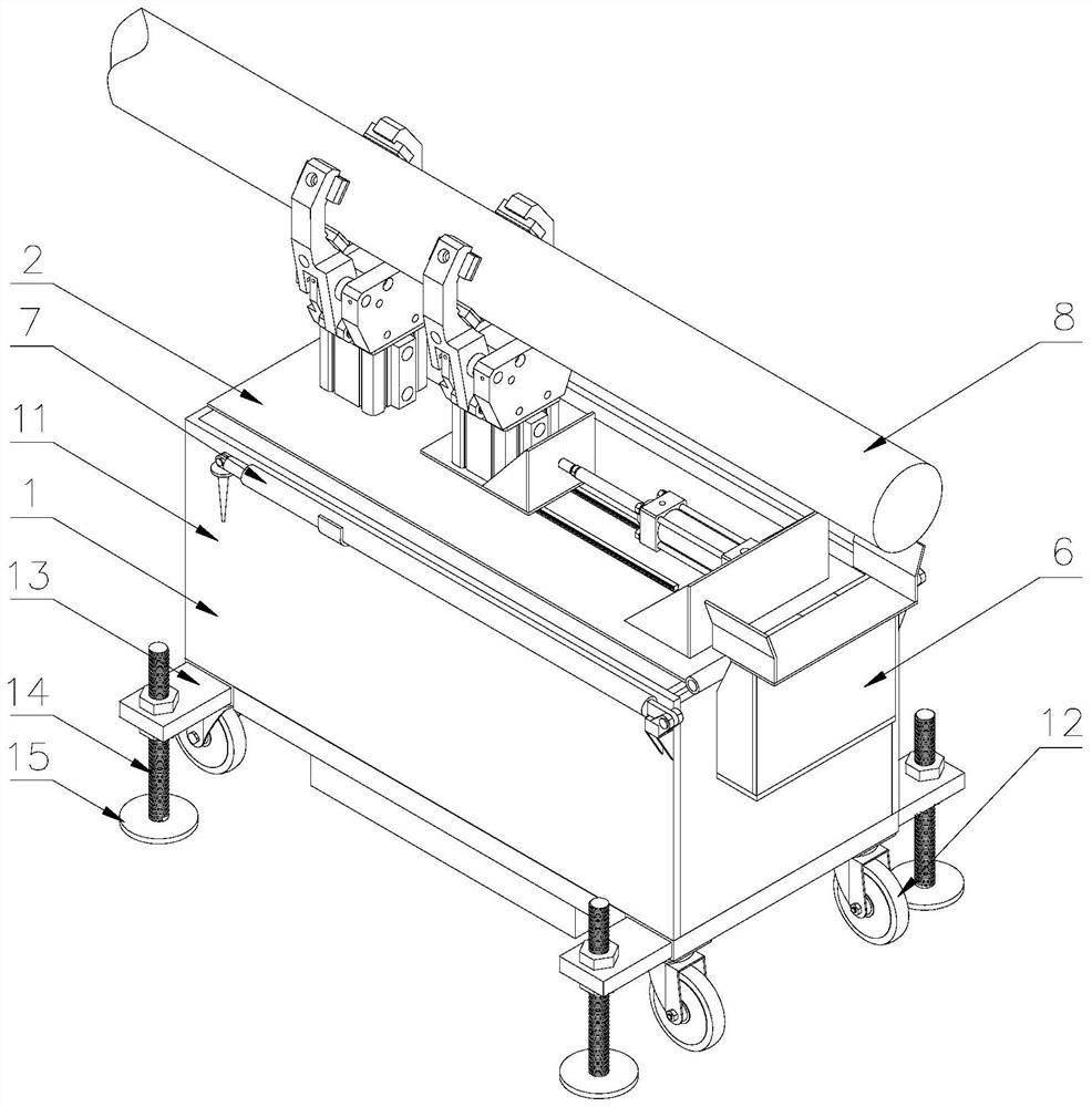
[0040] Attached below Figure 1-11 , clearly and completely describe the technical solutions in the embodiments of the present invention, obviously, the described embodiments are only some of the embodiments of the present invention, not all of them. Based on the embodiments of the present invention, all other embodiments obtained by persons of ordinary skill in the art without making creative efforts belong to the protection scope of the present invention.

[0041] In describing the present invention, it should be understood that the terms "longitudinal", "transverse", "upper", "lower", "front", "rear", "left", "right", "vertical", The orientations or positional relationships indicated by "horizontal", "top", "bottom", "inner", "outer", etc. are based on the orientations or positional relationships shown in the drawings, and are only for the convenience of describing the present invention, rather than indicating or It should not be construed as limiting the invention by impl...


PUM


Abstract

The invention discloses an electric pole erection device. A vehicle body comprises a tank and rolling wheels; the rolling wheels are arranged on the lower part of the tank; a connecting rod is arranged on one side in the tank; multiple first air cylinders are movably arranged on the connecting rod; first hinged joints are arranged at one end of the upper part of the tank; multiple second hinged joints are arranged at one end of a movable plate; the first hinged joints and the second hinged joints are movably connected through pin shafts; third hinged joints are arranged on one side of the lower part of the movable plate and are movably connected with one ends of the first air cylinder; and multiple clamping devices are arranged on one side of the upper part of the movable plate and comprise second air cylinders connected mutually, and clamping jaws. According to the electric pole erection device provided by the invention, the multiple clamping devices are arranged on the vehicle body,and a turnover device is arranged in the vehicle body; an electric pole is clamped by utilizing the clamping devices so as to be prevented from shaking when being erected; the turnover device is utilized for erecting the electric pole, so that the risk occurred by erecting the electric pole is reduced. The electric pole erection device provided by the invention is compact in structure and suitableto be used for electric pole erection in a rough country, and the difficulty in erecting the electric pole is reduced.

Description

technical field [0001] The invention belongs to the technical field of electric equipment, and in particular relates to a pole device for electric poles. Background technique [0002] As we all know, at present, most of the poles of power construction enterprises use cranes and other equipment poles. In order to improve work efficiency and reduce the physical exertion burden of operators, some iron parts, hardware, and insulators (strings) of the line are often advanced before the poles. It is installed at the corresponding position of the utility pole, and the trouble of mounting parts on the pole is avoided after the pole is erected. [0003] The traditional way of erecting electric poles is completely done manually or with the cooperation of cranes and manual construction. Manual cooperation with crane construction, manual cooperation with crane construction to excavate rod pits and fill soil compaction is also done manually, and the labor intensity is high. The partici...

Claims


Application Information

Patent Timeline
Patent Type & Authority Patents(China)
IPC IPC(8): E04H12/34
CPCE04H12/34E04H12/347
Inventor 盖丽娟秦利娄国赵宝强张翼李守桥李雪茹
Owner ZHANGQIU POWER SUPPLY CO OF STATE GRID SHANDONG ELECTRIC POWER CO
Learn More