
Hydraulic seal type steel gate

A hydraulic sealing and gate technology, which is applied in the field of steel gates, can solve problems such as large gap between steel gates and gate frames, safety accidents, water-stop rubber wear, etc., and achieve the effect of simple structure and reduced opening and closing force

Inactive Publication Date: 2019-11-19
江苏润源水务设备有限公司
View PDF0 Cites 1 Cited by
  • Summary
  • Abstract
  • Description
  • Claims
  • Application Information

AI Technical Summary

Problems solved by technology

[0002] At present, the water inlets and outlets of domestic municipal, environmental protection, electric power, drainage, sewage treatment, pumping stations, channel drainage and irrigation projects usually use cast iron gates to achieve the purpose of water stop. The existing steel gate structure includes gate frame, The gate and water-stop rubber, due to long-term opening and closing, will cause severe wear and tear of the water-stop rubber, making the gap between the steel gate and the gate frame larger and larger, resulting in poor water-stop effect and affecting the normal work of the steel gate performance, it is easy to cause safety accidents

Method used


Image

  • Hydraulic seal type steel gate
  • Hydraulic seal type steel gate
  • Hydraulic seal type steel gate

Examples


Embodiment Construction

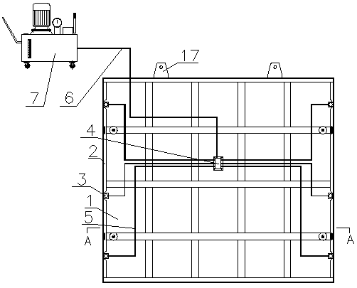
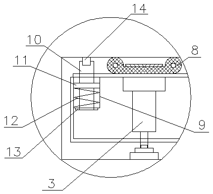
[0015] A hydraulically sealed steel gate, comprising a steel gate 1 and a gate frame 2, the steel gate 1 is placed in a gate groove inside the gate frame 2, and a plurality of hydraulic jacks 3 are arranged horizontally between the steel gate 1 and the gate frame 2 , the inside of the steel gate 1 is provided with a one-way diverter valve 4, the one-way diverter valve 4 is connected to the hydraulic jack 3 through a number of high-pressure hoses 5, the one-way diverter valve 4 is connected to a high-pressure electric oil pump 7 through a pipeline 6, and the steel gate 1 There are double P-shaped rubbers 8 between both sides of the upstream surface and the gate frame 2. The hydraulic jack 3 is located on the back of the double P-shaped rubbers 8. The piston rod of the hydraulic jack 3 penetrates the steel gate 1. Both sides of the gate 1 facing the water are respectively provided with holes, and a spring seat 9 is installed in the hole, and a telescopic rod 10 is arranged in the...


PUM


Abstract

The invention relates to a hydraulic seal type steel gate. The hydraulic seal type steel gate includes a steel gate body and a gate frame, the steel gate body is placed in a gate groove in the inner side of the gate frame, a plurality of hydraulic jacks are horizontally arranged between the steel gate body and the gate frame, the steel gate body is internally provided with a one-way flow guiding valve, the one-way flow guiding valve is connected with the hydraulic jacks, the one-way flow guiding valve is connected with a high-pressure electric oil pump, double-P-shaped rubber is disposed between the steel gate body and the gate frame, piston rods of the hydraulic jacks are in contact with the gate frame, holes are formed in both sides of the upstream face of the steel gate body, spring seats are installed in the holes, the spring seats are internally provided with telescopic rods, pressing plates located in the spring seats are fixedly disposed on the telescopic rods, springs sleevingthe telescopic rods are arranged between the pressing plates and the spring seats, the lower ends of the telescopic rods penetrate through the bottoms of the spring seats and are connected with adjusting nuts, the front ends of the telescopic rods are connected with rolling wheels through hinge pins, and L-shaped rubber sealed with the gate frame in an attached mode is disposed on the downstream face of the steel gate body. The hydraulic seal type steel gate has a simple structure, a good water stopping effect and a long service life, and can realize bidirectional water stop.

Description

technical field [0001] The invention relates to a steel gate, in particular to a hydraulic sealing steel gate. Background technique [0002] At present, the water inlets and outlets of domestic municipal, environmental protection, electric power, drainage, sewage treatment, pumping stations, channel drainage and irrigation projects usually use cast iron gates to achieve the purpose of water stop. The existing steel gate structure includes gate frame, The gate and water-stop rubber, due to long-term opening and closing, will cause severe wear and tear of the water-stop rubber, making the gap between the steel gate and the gate frame larger and larger, resulting in poor water-stop effect and affecting the normal work of the steel gate performance, it is easy to cause safety accidents. Contents of the invention [0003] In view of the above-mentioned defects, the purpose of the present invention is to provide a hydraulically sealed steel gate with simple structure, good wate...

Claims


Application Information

Patent Timeline
IPC IPC(8): E02B7/26E02B7/36E02B7/54
CPCE02B7/26E02B7/36E02B7/54
Inventor 姚能栋丁跃林高雅
Owner 江苏润源水务设备有限公司
Learn More