
Glue gun stable in pressure and flow

A technology of constant voltage and steady flow, glue gun, applied in the direction of coating, the device for coating liquid on the surface, etc., can solve the problems of flow pulsation of the glue pump, high price, difficult to promote in a large area, etc., to achieve a constant glue output, Accurate measurement and low cost effect

Pending Publication Date: 2019-11-19
重庆宏广机电设备有限公司
View PDF2 Cites 2 Cited by
  • Summary
  • Abstract
  • Description
  • Claims
  • Application Information

AI Technical Summary

Problems solved by technology

[0004] However, due to the flow pulsation of the glue pump, automatic glue application cannot achieve accurate metering
For this reason, in the prior art, equipment such as metering pumps and metering cylinders are used to ensure the output of glue to achieve precise metering. For example, the five-axis robot gluing equipment and process technology described in the patent application number CN201510398716.6, which uses metering Pump; as a metering high-pressure plunger pump described in patent application number CN201420639656.3, the metering parts are composed of metering cylinders, metering cylinder pistons and pusher sliders; the above two devices use metering pumps, metering cylinders, etc. Equipment and metering structures are complex to manufacture, expensive and difficult to promote in large areas

Method used


Image

  • Glue gun stable in pressure and flow
  • Glue gun stable in pressure and flow
  • Glue gun stable in pressure and flow

Examples


Embodiment Construction

[0024] The present invention will be further described below in conjunction with the accompanying drawings and embodiments.

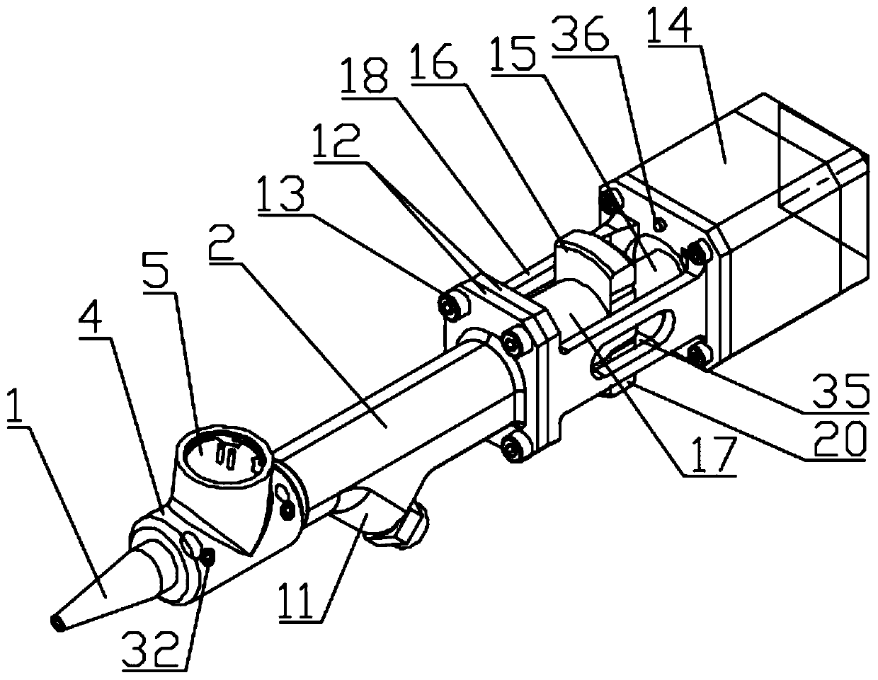
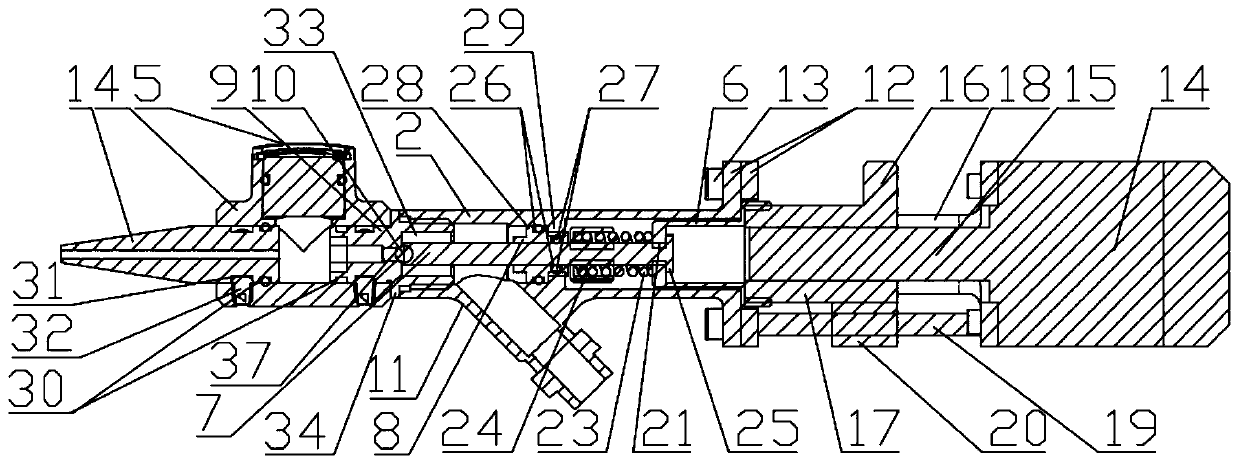
[0025] Such as Figure 1 to Figure 13 As shown, a stabilized pressure and stabilized flow glue gun includes a controller, a pusher and a glue head 1, the gun body 2 is connected to the pusher through a connecting frame, and also includes a pressure tube 4 and a pressure tube connected to the pressure tube 4. The transmitter 5 and the controller are respectively connected to the pressure transmitter 5 and the pushing device; the gun body 2 includes a connecting piece 6, a valve stem 7, a sealing guide 8, a valve core 9 and a valve fixed at the tail end of the valve stem 7 The ball 10; the spool 9 and the connecting piece 6 are respectively fixed on the two ends of the gun body 2, and the sealing guide 8 is fixed on the inner middle of the gun body 2; 6. One end is connected to the top of the valve stem 7, and the other end is fixedly connected to the pu...


PUM


Abstract

A glue gun stable in pressure and flow comprises a controller, a pushing device and a glue outlet. A gun body is connected with the pushing device through a connection frame. The glue gun stable in pressure and flow further comprises a pressure pipe and a pressure transmitter communicating with the pressure pipe. The controller is connected with the pressure transmitter and the pushing device. A connection piece, a valve rod, a seal guide piece, a valve element and a valve ball fixed to the tail end of the valve rod are arranged in the gun body. The valve element and the connection piece are fixed to the two ends of the gun body correspondingly. The seal guide piece is fixed to the middle in the gun body. The valve element, the pressure pipe and the glue discharge head are sequentially andfixedly connected in a sealed manner. One end of the connection piece is connected with the top end of the valve rod. The other end of the connection piece is fixedly connected with the pushing device. The valve rod penetrates through the seal guide piece. The valve ball at the tail end of the valve rod is matched with the valve element. On the gun body, a glue inlet pipe communicates between theseal guide piece and the valve element. The glue gun stable in pressure and flow has the beneficial effects that the cost is low, the pressure and flow of the glue gun can be guaranteed to be stable,so that the glue output amount is constant, and metering is accurate.

Description

technical field [0001] The invention relates to the field of gluing devices, in particular to a gluing gun with constant voltage and flow. Background technique [0002] Glue gun is a device used to spray or inject adhesive onto the surface of the adhered object. It may be used where glue is required. It is widely used in architectural decoration, electronic appliances, automobiles and auto parts, and ships. and container industries. [0003] In recent years, the government has vigorously advocated energy saving and emission reduction. This concept has been deeply rooted in the hearts of the people. Manufacturers have made great efforts to reform the use of glue and mechanical structures in response to this consumer psychology. Driven by this concept, automatic glue application technology has emerged. Compared with manual gluing and pneumatic gluing, the cost of automatic gluing is lower than them and higher in production efficiency, and the quality is better than manual glu...

Claims


Application Information

Patent Timeline
IPC IPC(8): B05C5/02B05C11/10
CPCB05C5/0225B05C11/1013
Inventor 徐新平路立勋
Owner 重庆宏广机电设备有限公司
Learn More