
Obstacle detection method and system

A technology of obstacle detection and variance, which is applied in the field of obstacle detection methods and systems, and can solve problems such as difficult obstacle and background distinction, inability to model background, and low accuracy

Active Publication Date: 2019-11-15
JIANGSU BIDE SCI & TECH CO LTD
View PDF8 Cites 12 Cited by
  • Summary
  • Abstract
  • Description
  • Claims
  • Application Information

AI Technical Summary

Problems solved by technology

[0003] In the prior art, due to the high speed of the vehicle, the background cannot be modeled. Therefore, it is not easy to distinguish the obstacle from the background by using the classical clustering algorithm to detect obstacles, so the detection accuracy is not high.

Method used


Image

  • Obstacle detection method and system
  • Obstacle detection method and system
  • Obstacle detection method and system

Examples


Embodiment Construction

[0059] The following will clearly and completely describe the technical solutions in the embodiments of the present invention with reference to the accompanying drawings in the embodiments of the present invention. Obviously, the described embodiments are only some, not all, embodiments of the present invention. Based on the embodiments of the present invention, all other embodiments obtained by persons of ordinary skill in the art without making creative efforts belong to the protection scope of the present invention.

[0060] In order to make the above objects, features and advantages of the present invention more comprehensible, the present invention will be further described in detail below in conjunction with the accompanying drawings and specific embodiments.

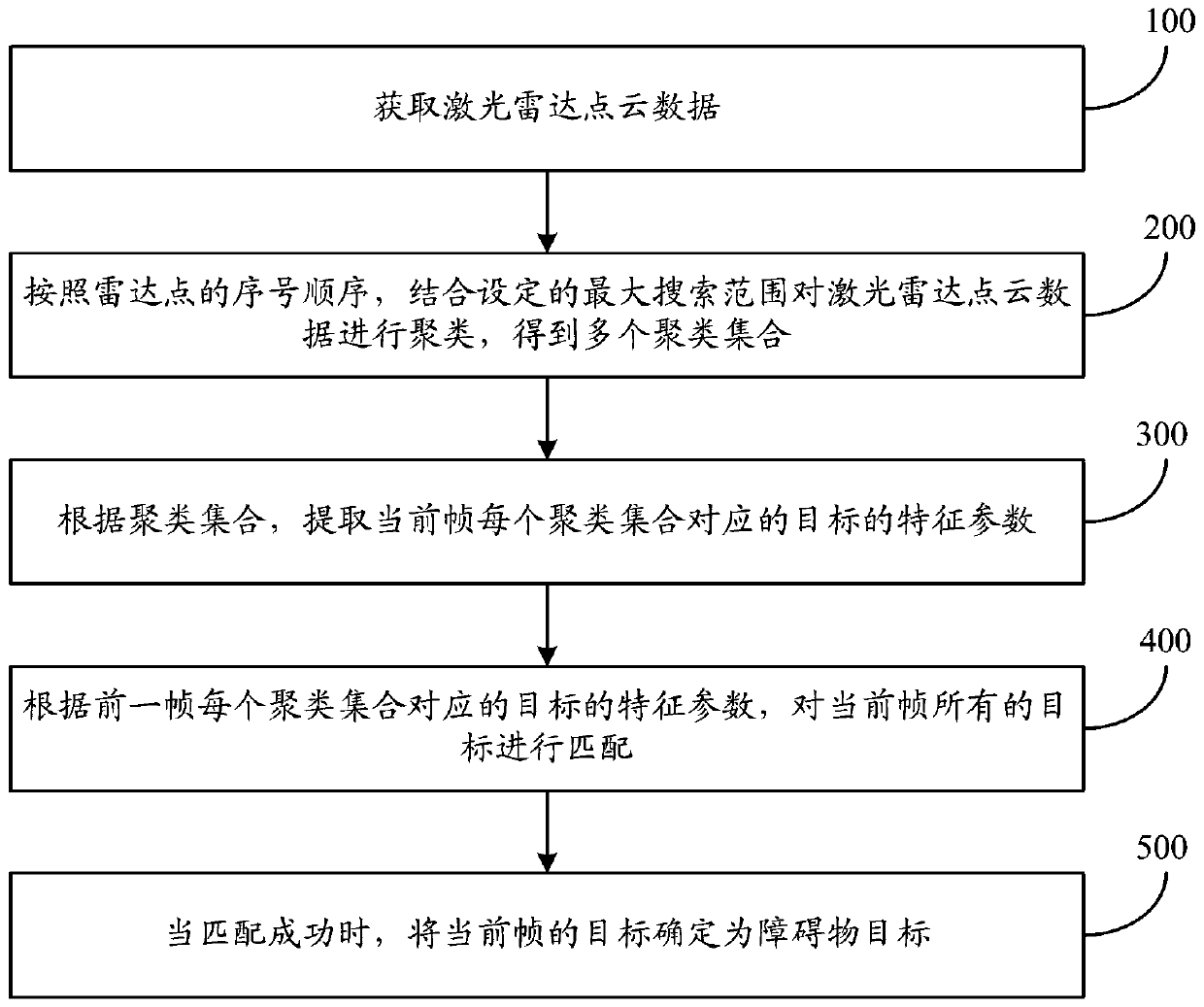
[0061] figure 1 It is a schematic flow chart of the obstacle detection method of the present invention. Such as figure 1 As shown, the obstacle detection method includes the following steps:

[0062] Step 100: ...


PUM


Abstract

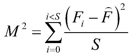
The invention discloses an obstacle detection method and system. The obstacle detection method comprises the following steps: acquiring laser radar point cloud data, wherein the laser radar point cloud data is detected by a single-line laser radar installed on a train; clustering the laser radar point cloud data according to the sequence number of the radar points in combination with a set maximumsearch range to obtain a plurality of clustering sets; extracting feature parameters of a target corresponding to each clustering set of the current frame according to the clustering sets, wherein the characteristic parameters comprise the number of radar points, an average azimuth angle, an average distance, a centroid position, average reflection intensity and reflection intensity variance; matching all the targets of the current frame according to the feature parameters of the targets corresponding to each clustering set of the previous frame; and when the matching succeeds, determining the target of the current frame as an obstacle target. According to the invention, the obstacle detection accuracy can be improved.

Description

technical field [0001] The invention relates to the field of track obstacle detection, in particular to an obstacle detection method and system. Background technique [0002] During normal driving on urban rails, it is necessary to detect obstacle targets in real time. At present, lidar is usually used to perceive medium-distance environmental objects and provide accurate distance information of environmental objects. The traditional lidar target detection mainly relies on the classic clustering algorithm. First, the clustering radius M is determined, and then a random seed point p is selected in the lidar point cloud image. i , calculate p i and all other radar points p i ,p i+1 …p n The distance between other radar points and p i Points whose distance is less than the clustering radius are added to the set V 1 {p i …p m}, and then in the set V 1 Select the next seed point in the point cloud image, which is not in V 1 The points in the distance are calculated, if...

Claims


Application Information

Patent Timeline
IPC IPC(8): G06K9/00G06K9/62
CPCG06V20/10G06V20/58G06F18/23
Inventor 蒋怡亮张奔宇顾青松姚伟宇陈皓晞张道
Owner JIANGSU BIDE SCI & TECH CO LTD
Learn More