
Beam broadening method based on arc-shaped equiphase surface

A technology of beam broadening and equal phase planes, which is applied in the field of phased array radar, can solve the problems of decreased detection distance, poor engineering realization, and difficult relationship correspondence, etc., and achieves easy engineering implementation, easy parameter debugging, and strong universality Effect

Active Publication Date: 2019-11-15
SHANGHAI RADIO EQUIP RES INST
View PDF10 Cites 0 Cited by
  • Summary
  • Abstract
  • Description
  • Claims
  • Application Information

AI Technical Summary

Problems solved by technology

[0004] In the existing technology related to beam broadening, in the document "Optimization method for beam broadening of planar phased array antenna" (Zhai Lixia, Zhang Liyun, "Science and Technology of Ships", 1995.3), the phase defocusing method is adopted, and the beam broadening The degree depends on the focal length, but the relationship between the two is difficult to correspond, and the engineering realization is not good
[0005] In the document "Application of SFFT in Array Antenna Beam Broadening Technology" (Chen Ding, Niu Baojun, He Bingfa, "Modern Radar", 2008.6), the beamforming method is used, and the continuous Fast Fourier Transform (Successive FastFourier Transforms, SFFT ) to achieve pattern synthesis to achieve the effect of beam broadening. This method needs to perform an iterative cycle according to the target, and the calculation is complicated. It is not suitable for systems that require fast real-time processing.
[0006] In the literature "Research on a Beam Broadening Method for Phased Array Antennas" (Gao Shichao, Bi Hongkui, Ship Electronic Engineering, 2009.12), the method of reducing the number of array elements and thereby reducing the aperture of the array is mainly suitable for passive antennas with centralized amplification and reception. Phased array, for the active phased array system in which each unit transmits and receives independently, reducing the number of array elements will lose reflected power, which will reduce the detection distance and affect system performance

Method used


Image

  • Beam broadening method based on arc-shaped equiphase surface
  • Beam broadening method based on arc-shaped equiphase surface
  • Beam broadening method based on arc-shaped equiphase surface

Examples


Embodiment Construction

[0026] The present invention is based on the design idea of ​​changing the linear equi-phase surface into an arc-shaped equi-phase surface, superimposing an additional phase difference value reflecting the arc-shaped wave path difference on the original linear space phase difference to realize a method of beam broadening.

[0027] The beam broadening method based on the arc equiphase surface provided by the present invention comprises the following steps:

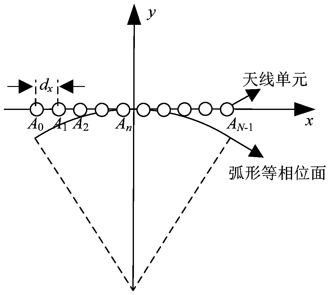
[0028] Step 1, such as figure 1 As shown in , it is assumed that there are N antenna units A numbered from 0 to N-1 in the entire array 0 ~A N-1 , arranged at equal intervals along the x-axis direction, and the distance between two adjacent cells is d x , taking the center of the array as the coordinate origin O, the x-axis coordinates of the nth array element can be expressed as (0≤n≤N-1).

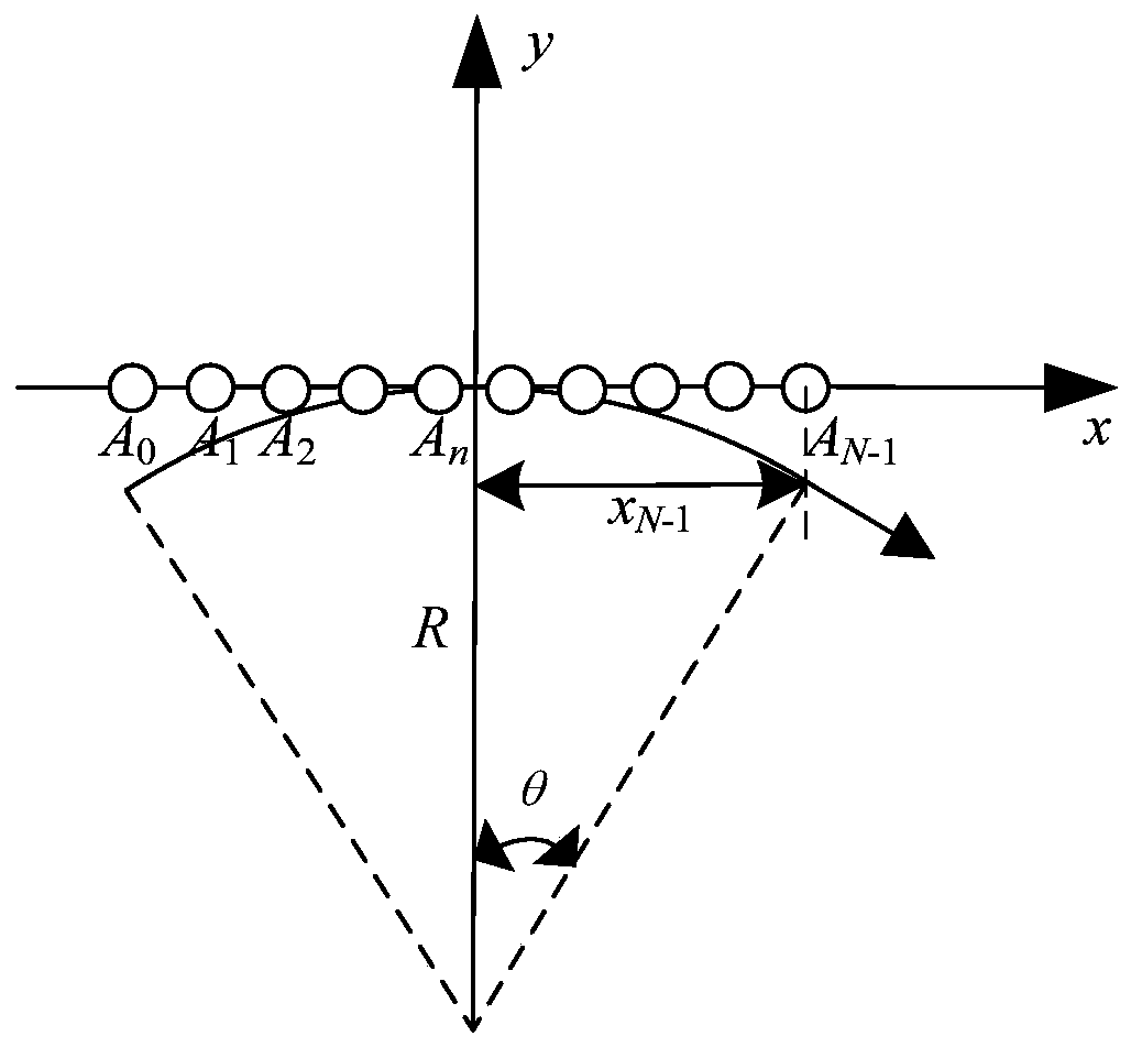
[0029] Step 2. Determine the radian angle θ, where θ is usually 10° to 30°.

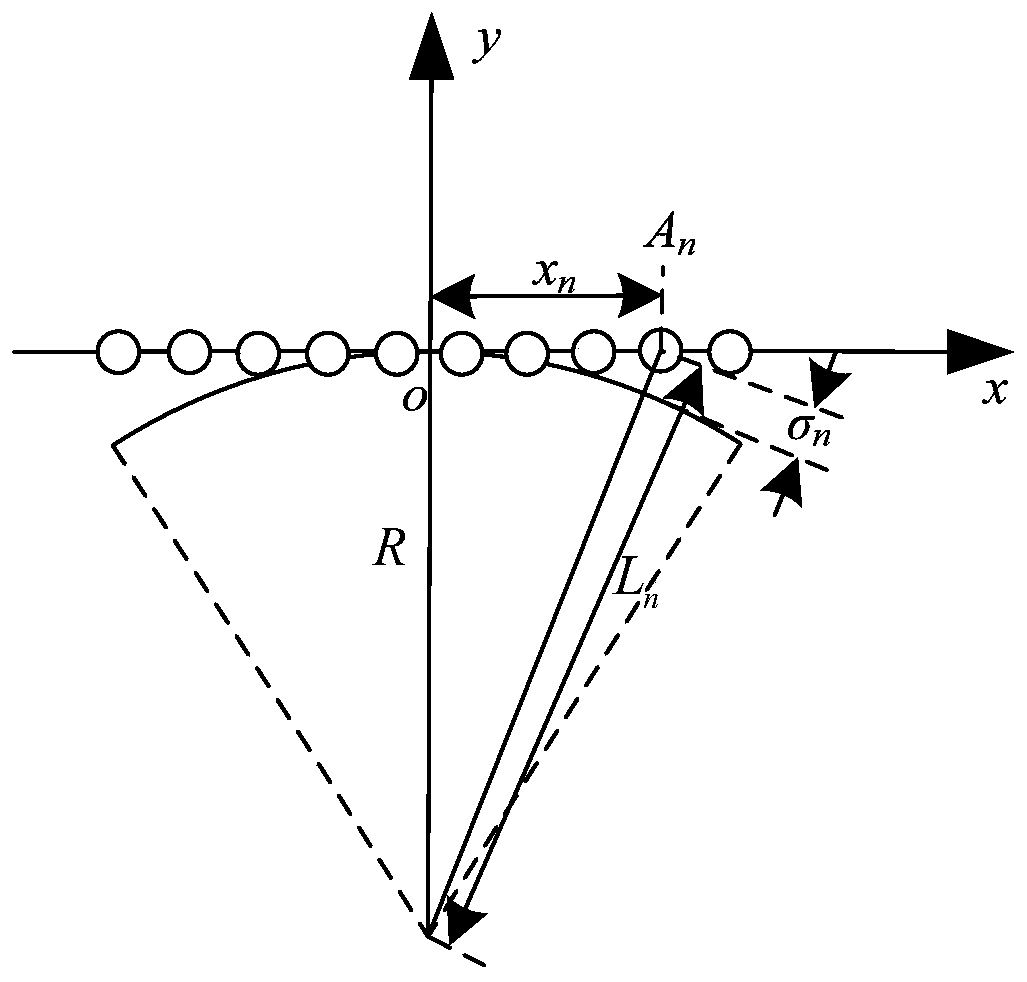
[0030] Step 3, if figure 2 As shown, according ...


PUM


Abstract

The invention relates to a beam broadening method based on an additional arc-shaped phase surface and belongs to phase change methods. Phase difference corresponding to the arc-shaped phase surface iscalculated, and the phase difference is directly overlapped into the spatial phase difference corresponding to an original beam pointing direction, so that beam broadening can be realized; cyclic iteration in beam forming is avoided, and the problem that the beam broadening degree is difficult to quantify is also solved; the method is simple, parameter debugging is easy, the real-time performanceis good, the universality is high, and engineering implementation is facilitated.

Description

technical field [0001] The invention belongs to the technical field of phased array radar, and relates to a beam broadening method based on an arc-shaped equiphase plane, which is applicable to any phased array system radar. Background technique [0002] Due to the advantages of flexible beam pointing and beam shape agility, phased array radar gradually replaces traditional mechanical scanning radar and is applied to various platforms such as ground, ship, and airborne. But in practice, phased array antennas are sometimes required to achieve beam broadening, such as when searching and tracking multiple targets in a specified space at the same time. At present, the commonly used methods include two categories, one is by reducing the number of array elements, and the other is based on changing the phase of the phased array antenna. The method based on changing the phase can be divided into beamforming method and phase dispersion method. There are two kinds of coke. [0003] ...

Claims


Application Information

Patent Timeline
IPC IPC(8): G01S7/02
CPCG01S7/02
Inventor 郭冬梅王珺李亚军汤继伟赵晗希李芬
Owner SHANGHAI RADIO EQUIP RES INST
Learn More