Power cycle acceleration test device and control method of mmc sub-module

A power cycle and accelerated test technology, applied in the field of power transmission and distribution, can solve the problems that the aging characteristics of sub-modules and consistent test results cannot be obtained

Active Publication Date: 2022-02-25
ELECTRIC POWER RESEARCH INSTITUTE, CHINA SOUTHERN POWER GRID CO LTD +1
View PDF14 Cites 0 Cited by
  • Summary
  • Abstract
  • Description
  • Claims
  • Application Information

AI Technical Summary

Problems solved by technology

[0004] The embodiment of the present invention provides an MMC sub-module power cycle acceleration test device and its control method, which can effectively solve the problem that the existing technology only tests and researches on a single IGBT and cannot obtain test results consistent with the aging characteristics of the sub-module under actual working conditions. question

Method used


Image

  • Power cycle acceleration test device and control method of mmc sub-module
  • Power cycle acceleration test device and control method of mmc sub-module

Examples


Embodiment 1

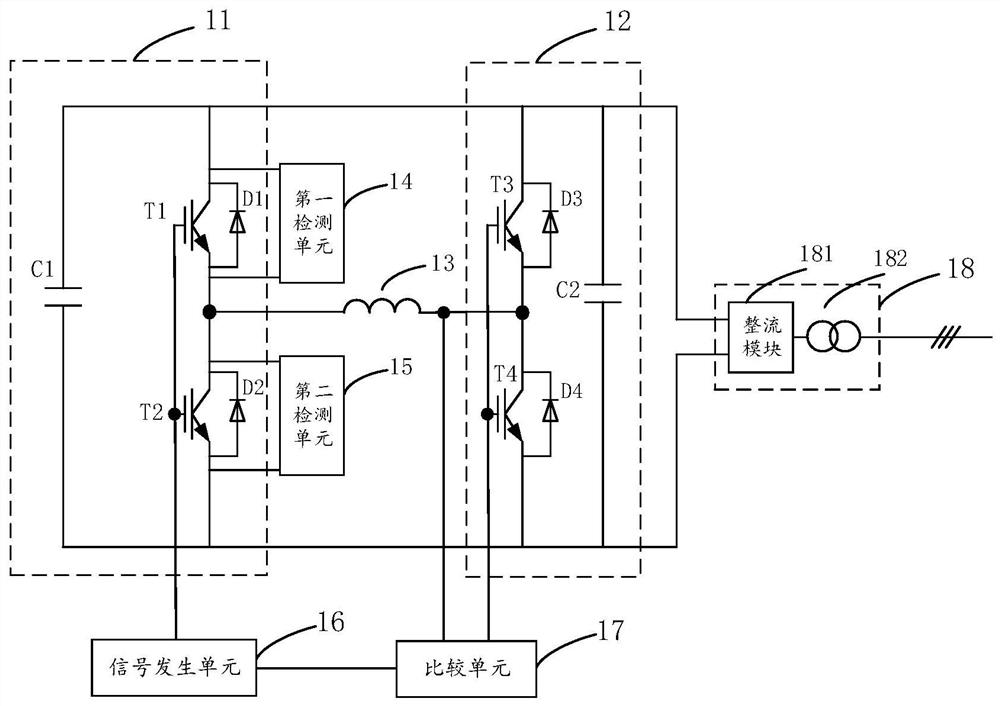
[0040] see figure 1, is a schematic structural diagram of an accelerated power cycle test device for an MMC sub-module provided in Embodiment 1 of the present invention. The accelerated power cycle test device for the MMC sub-module includes a tested unit 11, an accompanying test unit 12, and a reactance unit 13 , a first detection unit 14, a second detection unit 15, a signal generation unit 16 and a comparison unit 17;

[0041] The unit under test 11 is electrically connected in parallel to the two ends of the test unit 12; the first end of the reactance unit 13 is connected to the first end of the unit under test 11, and the second end of the reactance unit 13 End is connected with the first end of described accompanying test unit 12; Described first detection unit 14, described second detection unit 15 are all electrically connected with described tested unit 11; The first end of described signal generating unit 16 It is connected with the second end of the unit under tes...

Embodiment 2

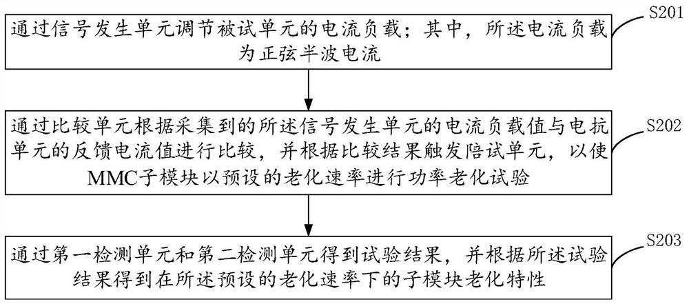
[0064] see figure 2 , is a schematic flowchart of a power cycle acceleration control method for an MMC sub-module provided in Embodiment 2 of the present invention, and the method includes the following steps S201 to S203.

[0065] S201. Adjust the current load of the unit under test through the signal generating unit; wherein, the current load is a half-sine wave current.

[0066] It should be noted that the signal generation unit 16 applies intermittent sinusoidal half-wave current loads with adjustable amplitude and period to the IGBT devices in the sub-modules according to the actual operating conditions of the modular multilevel converter.


PUM


Abstract

The invention discloses a power cycle acceleration test device of an MMC sub-module and a control method thereof, comprising a tested unit, an accompanying test unit, a reactance unit, a first detection unit, a second detection unit, a signal generating unit and a comparison unit; the tested unit The two ends of the accompanying test unit are electrically connected in parallel; the first end of the reactance unit is connected to the first end of the tested unit, and the second end of the reactance unit is connected to the first end of the accompanying test unit; the first detection unit, the second The detection unit is electrically connected to the tested unit; the first end of the signal generating unit is connected to the second end of the tested unit, and the second end of the signal generating unit is connected to the first end of the comparison unit; the second end of the comparison unit is connected to the reactance The third terminal of the unit is connected, and the third terminal of the comparison unit is connected to the second terminal of the accompanying test unit. The above structure can effectively solve the problem that the existing technology only tests and researches on a single IGBT, which leads to the inability to obtain sub-modules in accordance with actual working conditions. Problems with consistent test results for aging characteristics.

Description

technical field [0001] The invention relates to the technical field of power transmission and distribution, in particular to a power cycle acceleration test device of an MMC sub-module and a control method thereof. Background technique [0002] The power sub-module is the smallest energy storage and functional unit of the modular multi-level converter system. The aging degree of the sub-module directly represents the operating health status of the modular multi-level converter system. Ensuring the reliable operation of the sub-module is the guarantee The basis for the operational reliability of high-power power electronic converter systems. Judging from the current operation of flexible direct current transmission projects in operation, due to the lack of fault prediction and diagnosis mechanisms for sub-modules, the guarantee of project operation reliability is in a passive and unfavorable position. [0003] At present, there are literatures showing that foreign scholars m...

Claims


Application Information

Patent Timeline
Patent Type & Authority Patents(China)
IPC IPC(8): G01R31/00
CPCG01R31/003
Inventor 姬煜轲侯婷何智鹏李凌飞杨煜李岩易荣鲁挺余琼廖其艳
Owner ELECTRIC POWER RESEARCH INSTITUTE, CHINA SOUTHERN POWER GRID CO LTD
Why Eureka
Try Eureka