
Circular rotating disc mechanism for transferring microneedles

A turntable mechanism and micro-needle technology, used in conveyors, conveyor objects, transportation and packaging, etc., can solve problems such as high precision requirements, inability to meet production needs, automation, and small size.

Active Publication Date: 2019-11-15
SHANGHAI WORKPOWER TELECOM TECH
View PDF5 Cites 0 Cited by
  • Summary
  • Abstract
  • Description
  • Claims
  • Application Information

AI Technical Summary

Problems solved by technology

[0003] At present, the realization of automatic feeding of micro parts is a major trend in the development of China's manufacturing industry. However, due to the wide variety of micro parts, such as some micro needles with special processing requirements, especially some micro needles that cannot be clamped, due to their small size, High precision requirements add great difficulty to automatic processing and inter-process turnover. This type of microneedle needs to maintain accurate positioning during the process of turnover on the one hand to ensure smooth automatic loading and feeding. On the other hand, Also ensure that the surface of the needle is free from scratches and scratches
The existing problem is that the assembly work of this type of microneedle in the prior art is basically done manually, which cannot meet the growing production demand and the development trend of automation and intelligent production. Therefore, it is urgent to design a kind of micro needle Material and feeding mechanism to realize the automation of micro-needle feeding and feeding

Method used


Image

  • Circular rotating disc mechanism for transferring microneedles
  • Circular rotating disc mechanism for transferring microneedles
  • Circular rotating disc mechanism for transferring microneedles

Examples


Embodiment Construction

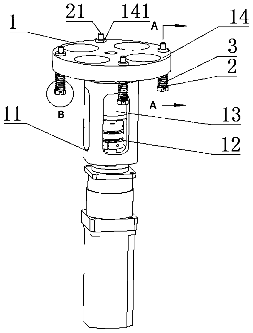
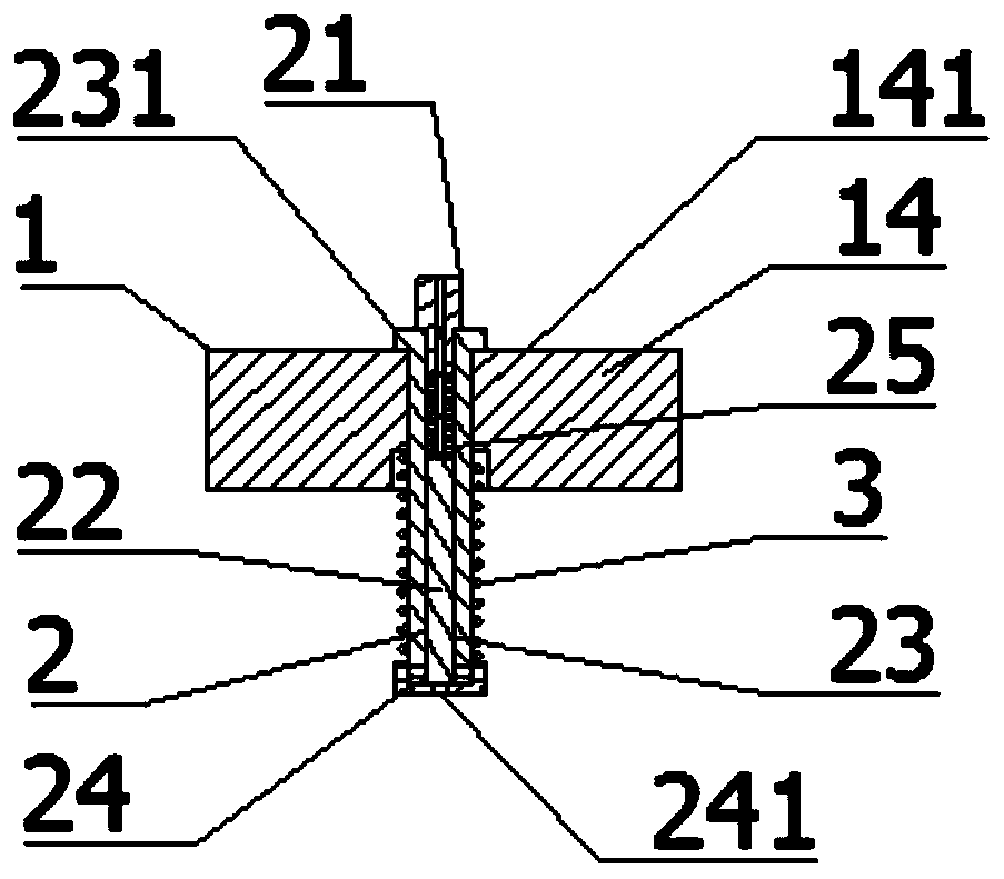
[0027] refer to figure 1 , figure 2 , the present invention includes a driving platform 1, a chuck assembly 2 and a second spring 3; the driving platform 1 is composed of a base 11, a stepping motor 12, a bearing 13 and a circular turntable 14; the base 11 is vertically arranged There is a frame member with a motor seat and a bearing seat; a rotating shaft is arranged on the center of the circular turntable 14, and four chuck assembly seats 141 are evenly distributed on the circumference; the bearing 13 is arranged on the bearing seat of the base 11, The stepping motor 12 is arranged on the motor base of the base 11 , and the circular turntable 14 is arranged on the top of the base 11 , the rotating shaft of the circular turntable 14 is hinged with the bearing 13 and connected with the output shaft of the stepper motor 12 .

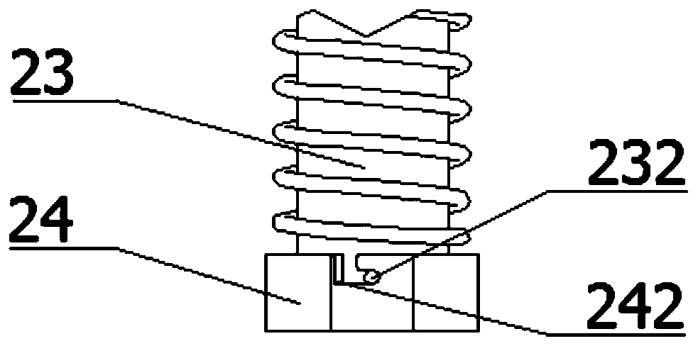
[0028] refer to figure 1 , figure 2 , image 3 , the chuck assembly 2 is composed of a chuck 21, a feeding push rod 22, a carrier 23, a cover 24 an...


PUM


Abstract

The invention discloses a circular rotating disc mechanism for transferring microneedles. The circular rotating disc mechanism comprises a driving platform, a chuck assembly and a second spring. The circular rotating disc mechanism adopts structures of the driving platform and the chuck assembly, wherein the driving platform is provided with a circular rotating disc and four chuck assembly seats,the chuck assembly is arranged on the chuck assembly seats, the circular rotating disc on the driving platform rotates to drive the chuck assembly to be circulated in a reciprocating mode between a feeding station and a conveying station, feeding and conveying work on the corresponding stations is completed through a chuck of the chuck assembly, a feeding jacking rod and a carrying table, and no abrasion and scratch is caused to the microneedles in the feeding and conveying processes. The circular rotating disc mechanism has the advantages that the structure is simple, universality is high, station conversion is fast and stable, and axial positioning of the microneedles is precise.

Description

technical field [0001] The invention relates to the technical field of tooling fixtures, which are used for process conversion of microneedles on an automatic production line, in particular to a circular turntable mechanism for revolving microneedles. [0002] technical background [0003] At present, the realization of automatic feeding of micro parts is a major trend in the development of China's manufacturing industry. However, due to the wide variety of micro parts, such as some micro needles with special processing requirements, especially some micro needles that cannot be clamped, due to their small size, High precision requirements add great difficulty to automatic processing and inter-process turnover. This type of microneedle needs to maintain accurate positioning during the process of turnover on the one hand to ensure smooth automatic loading and feeding. On the other hand, Also make sure that the surface of the needle is free from scratches and scratches. The exi...

Claims


Application Information

Patent Timeline
IPC IPC(8): B65G47/80
CPCB65G47/80B65G2201/0217
Inventor 陈明谭元英
Owner SHANGHAI WORKPOWER TELECOM TECH
Learn More