
Method and device for controlling current or power of power batteries

A power battery and current technology, applied in battery/fuel cell control devices, power devices, secondary battery charging/discharging, etc., can solve problems such as affecting the driving safety of drivers, vehicle failures, and interruption of high-voltage circuits.

Inactive Publication Date: 2019-11-15
NEUSOFT REACH AUTOMOBILE TECH (SHENYANG) CO LTD
View PDF6 Cites 3 Cited by
  • Summary
  • Abstract
  • Description
  • Claims
  • Application Information

AI Technical Summary

Problems solved by technology

[0003] However, when the BMS calculates the current or power allowed by the power battery, and / or when the VCU manages the current or power of the power battery, there will inevitably be calculation or control errors, which will make the control of the current or power of the power battery During the power process, if the current or power of the power battery exceeds the maximum current or power that the power battery can actually achieve, the power battery may tend to the cut-off voltage after a period of operation. Specifically, if the power battery is in a charging state, Then the voltage of the power battery may rise to the cut-off voltage. If the power battery is in a discharge state, the voltage of the power battery may drop to the cut-off voltage, which will cause the vehicle to appear when the power battery reaches the cut-off voltage based on the corresponding voltage protection strategy. The high-voltage circuit in the vehicle is interrupted, which will cause vehicle failure and may even affect the driving safety of the driver.

Method used


Image

  • Method and device for controlling current or power of power batteries
  • Method and device for controlling current or power of power batteries
  • Method and device for controlling current or power of power batteries

Examples


Embodiment Construction

[0042] For new energy vehicles, especially electric vehicles in new energy vehicles, errors will inevitably occur when BMS and VCU control the charging / discharging current or charging / discharging power of the power battery, for example, the control power calculated by BMS The current or power of the battery is too large, or the VCU controls the current or power of the power battery based on the signal provided by the BMS. current or power. In this way, after the power battery operates at this current or power for a period of time, the voltage of the power battery may tend to the cut-off voltage. Once the voltage of the power battery reaches the cut-off voltage, based on the corresponding voltage protection strategy in the vehicle, the high-voltage circuit in the vehicle is usually interrupted, thereby causing vehicle failure. For example, when the power battery is in a discharge state, interrupting the high-voltage circuit may cause It will lead to interruption of vehicle pow...


PUM


Abstract

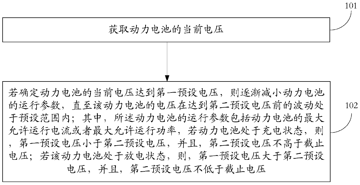
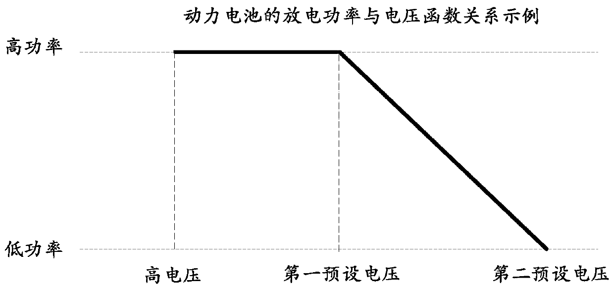
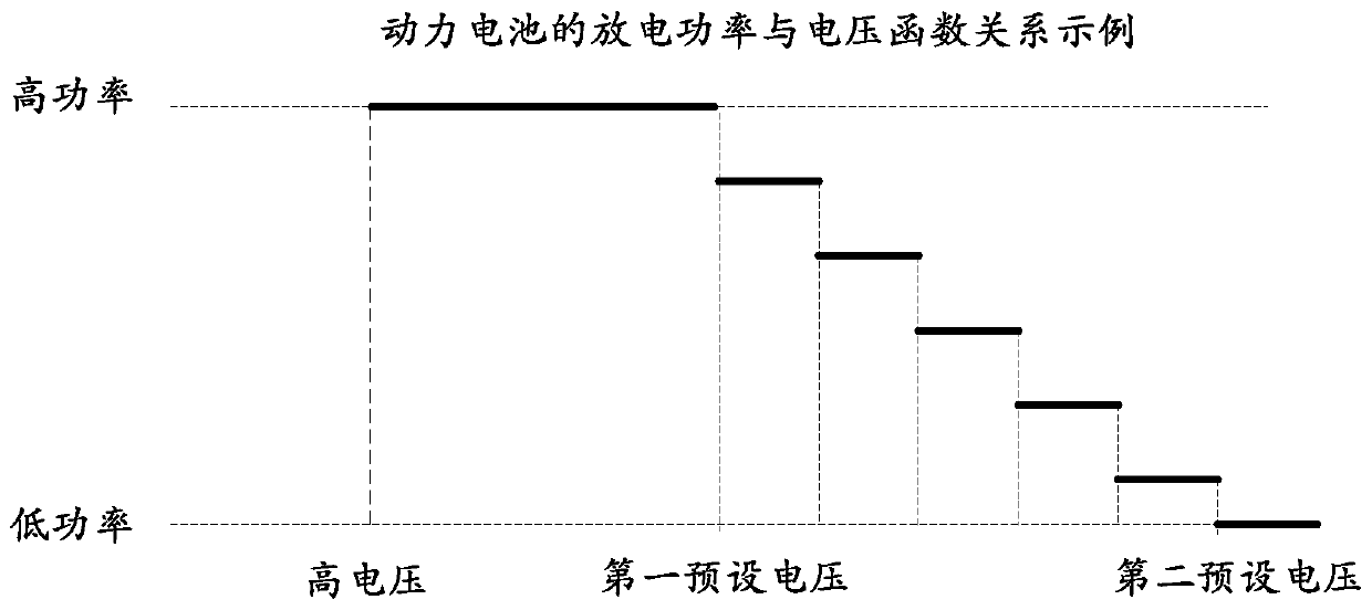
The invention discloses a method and device for controlling current or power of power batteries. The method comprises the steps of obtaining the current voltage of a power battery; and if the fact that the current voltage achieves first preset voltage is determined, gradually decreasing the maximum allowed operation current or maximum allowed operation power of the power battery until the fluctuation of the voltage of the power battery before achieving second preset voltage is located in a preset range. If the power battery is located in a charging state, the fist preset voltage is smaller than the second preset voltage and the second preset voltage is not higher than cut-off voltage; and if the power battery is located in a discharging state, the first preset voltage is greater than the second preset voltage and the second preset voltage is not lower than the cut-off voltage. Visibly, through gradually reducing the maximum allowed operation current or maximum allowed operation power of the power battery, the voltage of the power battery can be restrained from continuously changing to the cut-off voltage in time, so as to effectively avoid the condition that vehicle faults are caused as the voltage of the power battery achieves the cut-off voltage.

Description

technical field [0001] The present application relates to the technical field of power batteries, in particular to a method and device for controlling the current or power of a power battery. Background technique [0002] With the development of new energy vehicle technology, new energy vehicles such as pure electric vehicles and hybrid vehicles have gradually become an important means of transportation for people's daily travel. In new energy vehicles, the current (including discharge current and charging current) or power (including discharge power and charging power) of the power battery will be controlled by the battery management system (Battery Management System, BMS) and the whole vehicle in the new energy vehicle. The control of the Vehicle Control Unit (VCU), that is, the BMS can usually provide the maximum charging / discharging current or the maximum charging / discharging power signal of the power battery to the vehicle power system in the new energy vehicle, and is ...

Claims


Application Information

Patent Timeline
IPC IPC(8): B60L58/10B60L3/00H01M10/42H01M10/44
CPCB60L3/00B60L58/10H01M10/42H01M10/44H01M10/441Y02E60/10Y02T10/70
Inventor 金秋瑾
Owner NEUSOFT REACH AUTOMOBILE TECH (SHENYANG) CO LTD
Learn More