
A robot welding device and a method for obtaining welding seam trajectory

A technology of robot welding and acquisition method, applied in welding equipment, welding equipment, auxiliary devices, etc., can solve the problem of low requirements for operators

Active Publication Date: 2020-09-15
HENAN WEIHUA HEAVY MACHINE
View PDF7 Cites 1 Cited by
  • Summary
  • Abstract
  • Description
  • Claims
  • Application Information

AI Technical Summary

Problems solved by technology

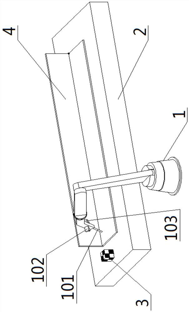
[0003] In order to overcome the deficiencies in the background technology, the present invention discloses a robot welding device and a method for obtaining weld trajectory; the robot welding device includes a welding robot, an XY workbench, a calibration reference block, and a computer; the welding robot is fixedly arranged on the XY At the front of the workbench, the welding robot and the XY workbench are controlled by a computer for linkage movement; wherein the welding robot includes a welding torch, a camera, and a 3D scanner fixedly arranged on the mechanical arm; the calibration reference block is fixedly arranged on the upper end surface of the XY workbench; In the welding preparation stage, the welding robot first takes pictures of the calibration reference block fixed on the XY worktable through the camera to obtain the current spatial position information of the robot; then obtains the 3D scanning and synchronous photography of the parts to be welded 3D model and picture; process the picture of the part to be welded and identify the template matching to obtain the weld picture; attach the weld picture to the corresponding position on the surface of the 3D model of the part to be welded, and the intersection of the weld and the two sides of the 3D model If the intersecting line coincides, the weld track is automatically generated according to the spatial coordinates of the two intersecting lines on the 3D model; when the automatic generation of the weld track fails, the operator can also directly calibrate on the 3D model of the part to be welded Weld track: This robotic welding device has the characteristics of high precision, high efficiency and low requirements for operators. At the same time, when the automatic generation of weld track fails, manual intervention can be performed directly on the 3D model of the welded part. , to generate high-precision weld trajectories; especially for the difficulty in obtaining weld trajectories of irregular curves on any surface in the past, it has also been perfectly solved

Method used


Image

  • A robot welding device and a method for obtaining welding seam trajectory

Examples


Embodiment Construction

[0026] The present invention can be explained in detail through the following examples, and the purpose of disclosing the present invention is to protect all technical improvements within the scope of the present invention.

[0027]A robot welding device, comprising a welding robot 1, an XY workbench 2, a calibration reference block 3, and a computer; the welding robot 1 is fixedly arranged at the front of the XY workbench 2, and the welding robot 1 and the XY workbench 2 are linked by computer control Movement; the welding robot 1 includes a welding torch 101, a camera 102, and a 3D scanner 103 fixedly arranged on the mechanical arm; the lens axis of the camera 102 is parallel to the wire feeding hole axis of the welding torch 101; the 3D scanner 103 is a laser 3D scanner; the plane where the axes of the 3D scanner 103 laser emitting lens and the two laser receiving lenses are located is parallel to the axis of the wire feeding hole of the welding torch 101, and perpendicular ...


PUM


Abstract

The invention provides a robot welding device and a method for acquiring a welding seam track. The robot welding device comprises a welding robot, an XY workbench, a calibration reference block and acomputer; the welding robot comprises a welding gun, a camera and a 3D scanner which are fixedly arranged on a mechanical arm; the calibration reference block is fixedly arranged on the upper end surface of the XY workbench; the welding robot firstly performs photographing on the calibration reference block which is fixedly arranged on the XY workbench through the camera so as to obtain current spatial position information of the robot; 3D scanning and synchronous photographing is carried out on a to-be-welded part to obtain a three-dimensional model and a picture of the to-be-welded part; processing and template matching identification are carried out on the picture of the to-be-welded part to obtain a welding seam picture; and the welding seam picture is attached to a corresponding position on the surface of the three-dimensional model of the to-be-welded part, and if the intersecting line of the two intersecting planes on the three-dimensional model coincides with the welding seam,a welding seam track is automatically generated according to the spatial coordinate of intersecting line of the two intersecting planes on the three-dimensional model.

Description

technical field [0001] The invention relates to the technical field of robot automatic welding, in particular to a robot welding device and a method for acquiring a welding seam trajectory. Background technique [0002] The existing robot welding device needs to manually guide the robot to generate the weld trajectory in the welding preparation stage, or obtain the weld trajectory through camera and image recognition; among them, the method of manually guiding the robot to generate the weld trajectory has low accuracy, Problems such as low efficiency and high requirements for operators are gradually being eliminated; among them, the method of obtaining weld trajectory through image recognition is affected by the interference of various ambient lights on site and the accuracy and reliability of existing recognition methods. In some cases, the problem that the weld trajectory cannot be obtained accurately; especially when the weld of the part to be welded is an irregular curve...

Claims


Application Information

Patent Timeline
Patent Type & Authority Patents(China)
IPC IPC(8): B23K37/00B23K9/32B23K9/127B23K9/095
CPCB23K9/095B23K9/0953B23K9/127B23K9/32B23K37/00
Inventor 聂福全杨卫铁张振强王永强吴庆宁段君飞吴庆富
Owner HENAN WEIHUA HEAVY MACHINE
Learn More