
An electromagnetic compatibility box

A compatible box and electromagnetic technology, applied in the direction of electrical components, magnetic field/electric field shielding, electrical equipment structural parts, etc., can solve problems such as electromagnetic interference, failure to meet shielding requirements, failure to pass electromagnetic compatibility tests, etc., to achieve enhanced structural strength, Good electromagnetic compatibility shielding function, the effect of preventing adverse effects

Active Publication Date: 2020-04-07
SHANDONG INST FOR PROD QUALITY INSPECTION
View PDF6 Cites 0 Cited by
  • Summary
  • Abstract
  • Description
  • Claims
  • Application Information

AI Technical Summary

Problems solved by technology

[0003] However, traditional EMC shielding devices usually use only one layer of metal plate to make the shielding cavity
Because this structure is relatively simple, it can only be applied to low-frequency electromagnetic shielding, and often cannot pass the electromagnetic compatibility test. In actual use, it is easy to cause electromagnetic interference with other electromagnetic equipment.
Therefore, the traditional shielding structure can no longer meet the shielding requirements in complex electromagnetic environments

Method used


Image

  • An electromagnetic compatibility box
  • An electromagnetic compatibility box
  • An electromagnetic compatibility box

Examples


Embodiment Construction

[0020] In order to make the object, technical solution and advantages of the present invention clearer, the present invention will be further described in detail below in conjunction with the accompanying drawings and embodiments. It should be understood that the specific embodiments described here are only used to explain the present invention, not to limit the present invention.

[0021] In order to facilitate the understanding of the electromagnetic compatibility box provided by the embodiment of the present invention, firstly explain the application scenarios of the electromagnetic compatibility box provided by the embodiment of the present application. The electromagnetic compatibility box provided by the embodiment of the present application is used to install electrical or electronic equipment, so that electrical or In a space with a complex electromagnetic environment, electronic equipment can meet the normal work of the design requirements with a specified safety facto...


PUM


Abstract

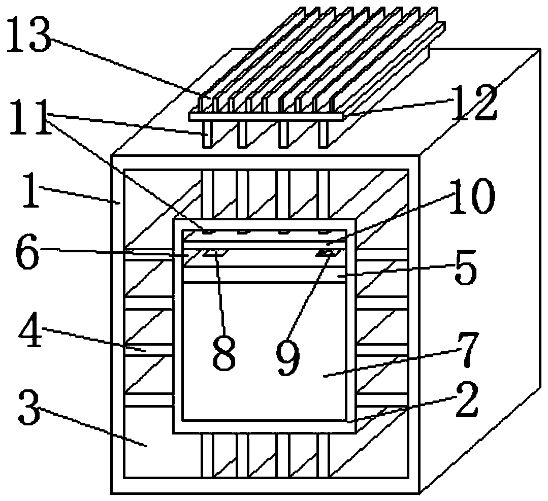
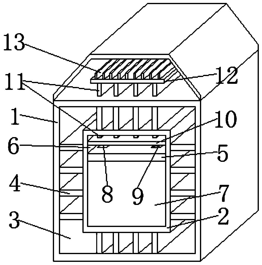
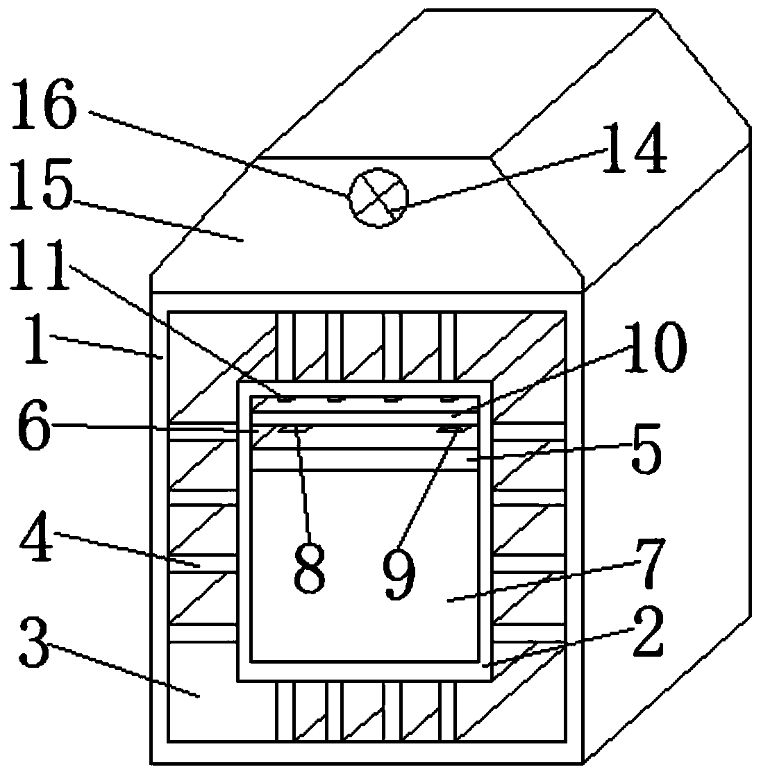
The invention provides an electromagnetic compatibility box. The box comprises an outer box and an inner box arranged in the outer box, and a shielding cavity is formed between the outer box and the inner box. A plurality of partition plates are arranged in the shielding cavity and divide the shielding cavity into a plurality of sub-shielding cavities, wherein the interior of each sub-shielding cavity is provided with a shielding layer; a horizontal partition plate is arranged in the inner box and divides the inner box into an upper heat dissipation cavity and a lower installation cavity. Theinvention has the beneficial effects that the structural strength of the box can be enhanced, and a good electromagnetic compatibility shielding function is achieved; the box is suitable for shieldingvarious electromagnetic waves; meanwhile, the rain-proof and heat dissipation functions are achieved, and the adverse effects of dust on installed electrical or electronic equipment can be effectively prevented in the heat dissipation process.

Description

technical field [0001] The invention relates to the technical field of electromagnetic compatibility, in particular to an electromagnetic compatibility box. Background technique [0002] Electromagnetic Compatibility The ability of various electrical or electronic equipment to meet the design requirements with a specified safety factor in a space with a complex electromagnetic environment, also known as electromagnetic compatibility, its meaning includes: First, the electromagnetic compatibility between electronic systems or equipment The mutual consideration in the environment; the second is that the electronic system or equipment can work normally in accordance with the design requirements in the natural electromagnetic environment. [0003] However, traditional EMC shielding devices usually only use one layer of metal plate to make the shielding cavity. Because this structure is relatively simple, it is only suitable for low-frequency electromagnetic shielding, and often...

Claims


Application Information

Patent Timeline
Patent Type & Authority Patents(China)
IPC IPC(8): H05K9/00H05K7/20
CPCH05K7/20136H05K7/20409H05K9/0007
Inventor 窦慧李洪亮
Owner SHANDONG INST FOR PROD QUALITY INSPECTION
Learn More