Rotating signal transmission mechanism and platform of unmanned aerial vehicle
A technology for transmitting signals and conductive structures, applied in the field of unmanned aerial vehicles, can solve problems such as line winding, and achieve the effect of expanding the shooting angle
- Summary
- Abstract
- Description
- Claims
- Application Information
AI Technical Summary
Problems solved by technology
Method used
Image

Examples
Embodiment 1
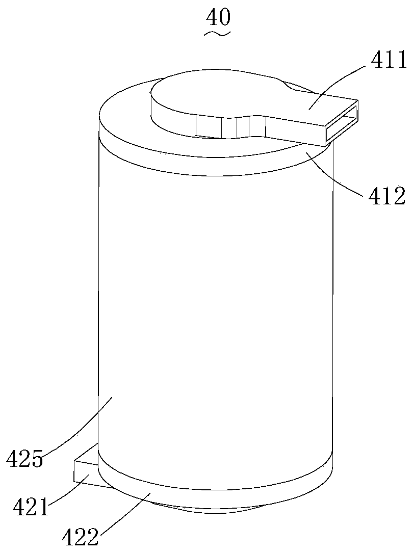
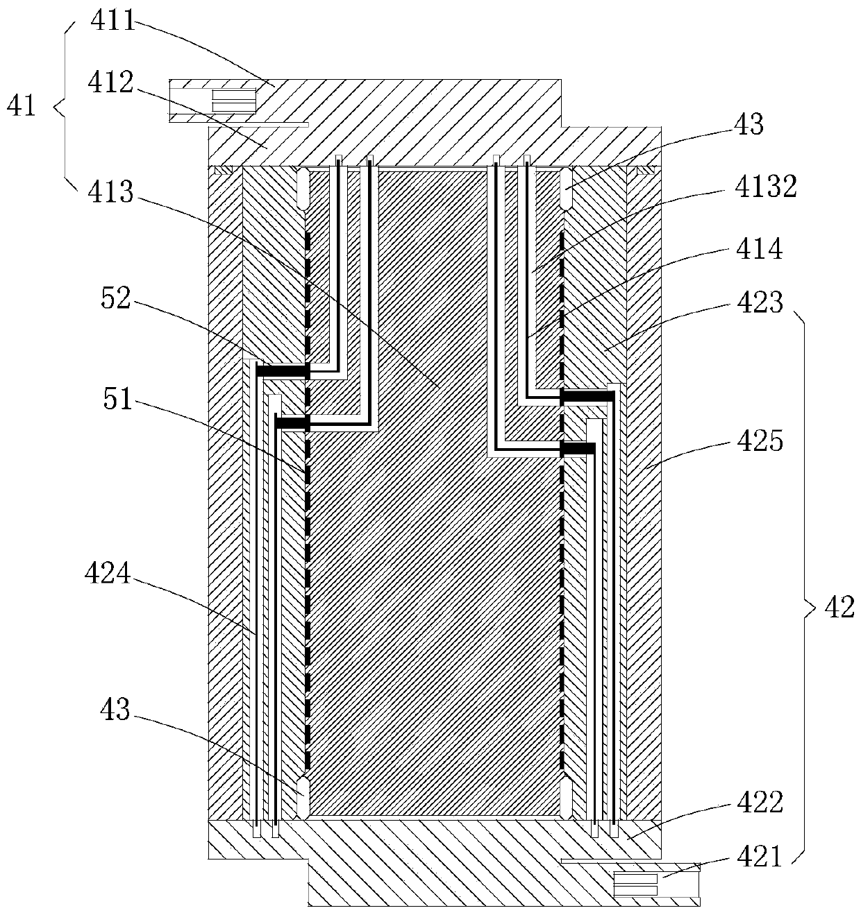
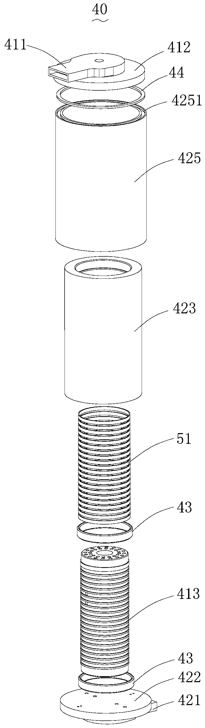
[0036] see Figure 1-6 , Embodiment 1 of the present invention discloses a rotary transmission signal mechanism 40, comprising a first wiring assembly 41 having a first wiring terminal 411 and a second wiring assembly 41 having a second wiring terminal 421 and being rotatably connected to the first wiring assembly 41 component 42, the first wiring component 41 is provided with several first conductive structures 51 arranged at intervals and electrically connected to the first terminal 411, and the second wiring assembly 42 is provided with several intervals arranged and all connected to the second wiring The terminal 421 is electrically connected to the second conductive structure 52 , the first conductive structure 51 is a ring-shaped conductive structure, the second conductive structure 52 is a brush, and each brush is correspondingly in contact with a ring-shaped conductive structure.
[0037] In this design, since the signal is transmitted through the first conductive stru...
Embodiment 2
[0051] see Figure 7-9 Embodiment 2 of the present invention provides a rotation transmission signal mechanism 70. The rotation transmission signal mechanism 70 provided in Embodiment 2 of the present invention is the same as the rotation transmission signal mechanism 40 provided in Embodiment 1 of the present invention in that:
[0052] The rotary transmission signal mechanism 70 of this embodiment also includes a first wiring assembly 71 having a first wiring terminal 711 and a second wiring assembly 72 having a second wiring terminal 721 and being rotatably connected to the first wiring assembly 71, the first wiring assembly 71 is also provided with several first conductive structures 81 that are arranged at intervals and are electrically connected to the first connection terminal 711. The second connection assembly 72 is also provided with several intervals and are electrically connected with the second connection terminal 721. The second conductive structure 82, the first...
Embodiment 3
[0060] see Figure 7-11 , the third embodiment of the present invention discloses a drone platform 100, including a mount 101, a first shaft arm 102, a second shaft arm 103, a motor 104 and as described in the first or second embodiment In this embodiment, the rotation signal transmission mechanism 70 disclosed in the second embodiment is taken as an example for illustration. Mounting seat 101 is used for installing and fixing the fuselage of unmanned aerial vehicle, and first shaft arm 102 is connected with mounting seat 101, and second shaft arm 103 is rotationally connected with first shaft arm 102, and camera is installed on the second shaft arm 103, The motor 104 is installed on the first shaft arm 102 for driving the second shaft arm 103 to rotate relative to the first shaft arm 102, and the rotation signal transmission mechanism 70 is installed between the first shaft arm 102 and the second shaft arm 103 for Communication between drone body and camera.
[0061]Specifi...
PUM
 Abstract
Description
Claims
Application Information
 - R&D
- Intellectual Property
- Life Sciences
- Materials
- Tech Scout
- Unparalleled Data Quality
- Higher Quality Content
- 60% Fewer Hallucinations
Browse by: Latest US Patents, China's latest patents, Technical Efficacy Thesaurus, Application Domain, Technology Topic, Popular Technical Reports.
© 2025 PatSnap. All rights reserved.Legal|Privacy policy|Modern Slavery Act Transparency Statement|Sitemap|About US| Contact US: help@patsnap.com