
Display device

A display device and display area technology, which is applied in the direction of instruments, computer components, printing image acquisition, etc., can solve the problems of poor optical quality of display devices, and achieve the effect of improving optical quality and reducing display differences

Active Publication Date: 2019-11-12
XIAMEN TIANMA MICRO ELECTRONICS
View PDF6 Cites 12 Cited by
  • Summary
  • Abstract
  • Description
  • Claims
  • Application Information

AI Technical Summary

Problems solved by technology

As a result, there is a difference in display effect between the sensor installation area and the surrounding display area, resulting in poor optical quality of the display device as a whole

Method used


Image

  • Display device
  • Display device
  • Display device

Examples


Embodiment Construction

[0025] The present invention will be further described in detail below in conjunction with the accompanying drawings and embodiments. It should be understood that the specific embodiments described herein are only used to explain the present invention, but not to limit the present invention. In addition, it should be noted that, for the convenience of description, the drawings only show some but not all structures related to the present invention.

[0026] In the related art, the technology based on optical fingerprint recognition is mainly used in active / active matrix organic light-emitting diode (Active-matrix organic light-emitting diode, AMOLED) display devices. In the AMOLED display device, the working principle of the optical fingerprint recognition can be as follows: the light emitted by the organic light-emitting diode is used as the light irradiated on the fingerprint surface in the fingerprint recognition technology. The difference is achieved by the fingerprint rec...


PUM

PropertyMeasurementUnit
angleaaaaaaaaaa
angleaaaaaaaaaa

Abstract

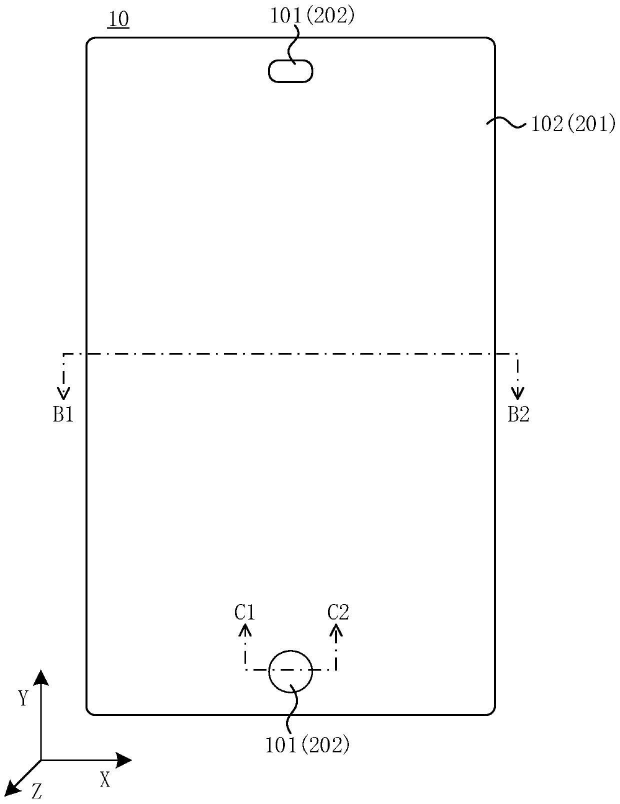
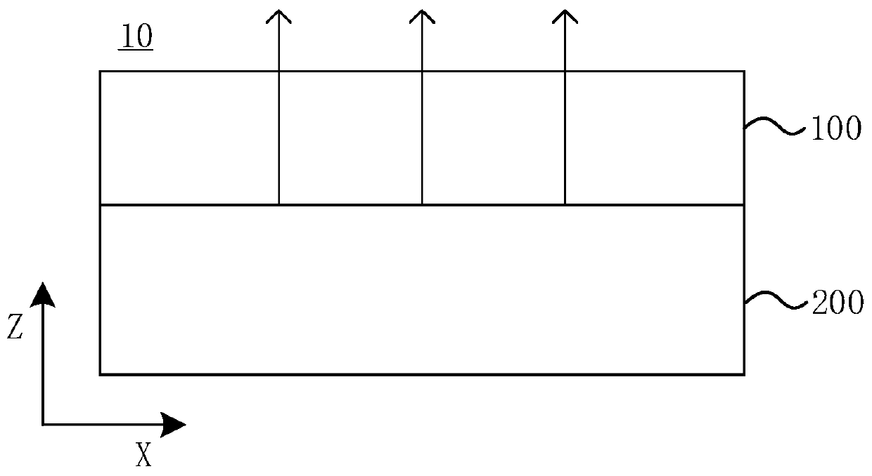
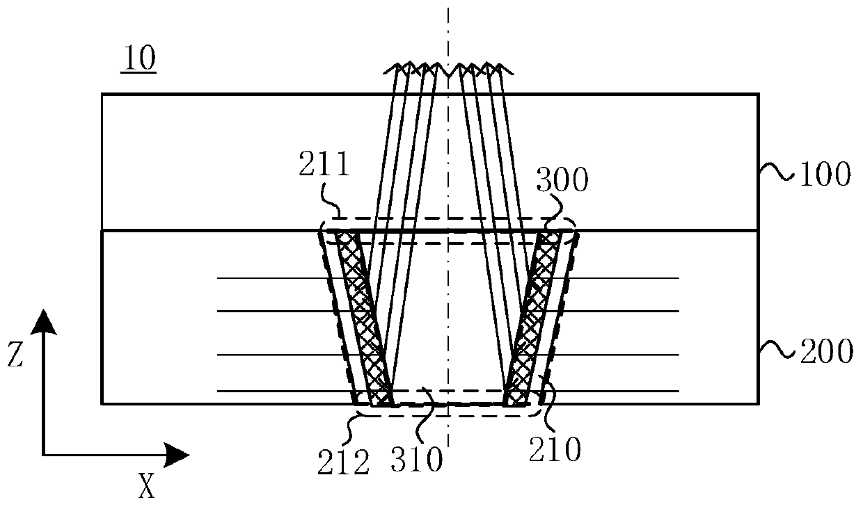
An embodiment of the invention discloses a display device. The display device comprises a display panel and a backlight module; the display panel is arranged on the light emitting side of the backlight module; the display panel comprises at least one sensor setting area and a display area surrounding the sensor setting area; the backlight module comprises a backlight area and at least one hole digging area; the backlight area is arranged corresponding to the display area, and the hole digging area and the sensor setting area are arranged in a one-to-one correspondence mode; the hole digging area is provided with a light transmission through hole penetrating through the backlight module in the first direction, wherein the first direction is the direction of the backlight module pointing tothe display panel; and the display device also comprises a light supplementing structure which is arranged in the light transmission through hole, and the light supplementing structure is used for adjusting the light emitted from the backlight module to the light supplementing structure to irradiate the sensor setting area corresponding to the light transmission through hole. According to the technical scheme provided by the embodiment of the invention, the light rays irradiated to the sensor setting area can be compensated by the light supplementing structure, so that the optical taste of thedisplay device can be improved.

Description

technical field [0001] The present invention relates to the field of display technology, and in particular, to a display device. Background technique [0002] With the development of display technology, in order to improve user experience, high screen ratio has gradually become an important development direction of display devices. The screen ratio can be understood as the ratio of the visible area of ​​the display device to the total area of ​​the plane on which it is located. In order to increase the screen ratio, it is necessary to reduce the area occupied by the border area of ​​the display device, thereby reducing the area occupied by the non-display area; The modules arranged in the frame area (for example, the front camera, the front flash, the earpiece, etc. on the mobile phone) are arranged in the non-display area. [0003] Generally, a sensor setting area is set within the display area of ​​the display device, and the structure of at least part of the film layer ...

Claims


Application Information

Patent Timeline
Patent Type & Authority Applications(China)
IPC IPC(8): G02F1/1333G02F1/13357G02B6/00G06K9/00
CPCG02F1/1333G02F1/1336G02F1/133606G02F1/133605G02B6/0051G02B6/0053G02B6/0055G06V40/1318
Inventor 马雄斌
Owner XIAMEN TIANMA MICRO ELECTRONICS
Learn More