
Feed screw nut pair, safety transmission device and lifting mechanism

A technology of screw nut pair and driving device, which is applied in the direction of transmission device, hoisting device, mechanical equipment, etc., can solve problems such as damage, unsafe transmission mechanism, deformation of screw nut pair, etc., and achieve the effect of avoiding head-to-head

Pending Publication Date: 2019-11-12
SHENZHEN ZHAOWEI MACHINERY&ELECTRONICS CO LTD
View PDF0 Cites 0 Cited by
  • Summary
  • Abstract
  • Description
  • Claims
  • Application Information

AI Technical Summary

Problems solved by technology

[0002] In the existing micro-transmission technology, the drive device is often used to drive the screw nut pair to achieve power conversion, which solves the transmission problem. However, there are unsafe factors in the existing transmission mechanism, which are specifically reflected in: when one end of the load is loaded When it is too large, there is no mechanism to relieve this state, causing the driving device to still work, or even increase the horsepower. At this time, it is very likely to cause deformation of the screw nut pair; or cause deformation of the corresponding transmission device, breakage; what is more, it will cause damage to the drive unit

Method used


Image

  • Feed screw nut pair, safety transmission device and lifting mechanism
  • Feed screw nut pair, safety transmission device and lifting mechanism
  • Feed screw nut pair, safety transmission device and lifting mechanism

Examples


Embodiment 1

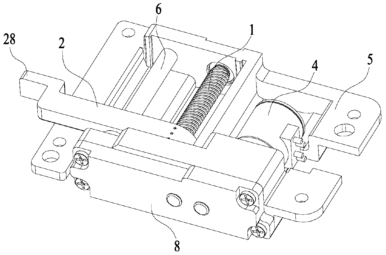
[0037] see Figure 4 to Figure 7 , A preferred embodiment of the present invention discloses a screw nut pair, which includes a screw 1, a nut 2 and a protection mechanism.

[0038] see Figure 4 and Figure 5 , the nut 2 is provided with a screw hole 21 , the screw 1 is penetrated in the screw hole 21 , and the nut 2 can slide back and forth along the axial direction of the screw 1 .

[0039] see Figure 6 and Figure 7 , the protection mechanism is arranged in the screw hole 21 of the nut 2 , and the protection mechanism includes a mounting hole 22 , a spring 23 and a marble 24 .

[0040] The mounting hole 22 is opened in the screw hole 21, and the mounting hole 22 is facing the outer surface of the screw rod 1, the spring 23 and the marble 24 are all accommodated in the mounting hole 22, and the spring 23 is used to provide an elastic force, so that the marble 24 extends out of the installation hole 22 and then resists in the threaded groove of the screw rod 1 .

[00...

Embodiment 2

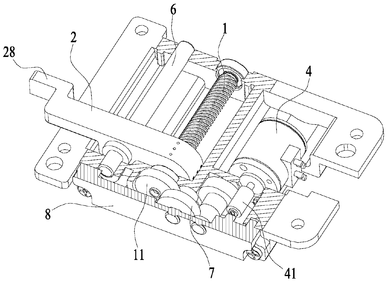
[0055] see Figure 1 to Figure 7 , This embodiment discloses a safety transmission device, which includes a driving device, a transmission assembly 7 and a screw nut pair, and the screw nut pair is the screw nut pair described in Embodiment 1. In this embodiment, the driving device is a driving motor 4 .

[0056] The transmission assembly 7 is installed between the drive motor 4 and the screw nut pair, and is connected to the drive motor 4 and the screw nut pair respectively.

[0057] Specifically, in one of the embodiments, the transmission assembly 7 is composed of a plurality of gears meshed with each other, and the plurality of gears are meshed with the driving motor 4 and the screw 1 respectively. Specifically, the rotating shaft of the driving motor 4 is fixedly connected with a driving gear 41 , and the driving end of the screw 1 is fixedly connected with a driving gear 11 .

[0058] In some other embodiments, a gearbox is provided between the drive motor 4 and the sc...

Embodiment 3

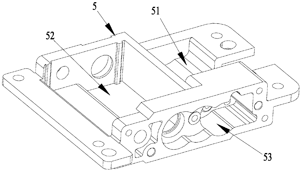
[0066] see Figure 1 to Figure 7 , this embodiment discloses a lifting mechanism, which includes a shell base 5 and a safety transmission device, the safety transmission device is the safety transmission device described in Embodiment 2, and the safety transmission device further includes a drive motor 4, a transmission assembly 7 and the screw nut pair described in Embodiment 1.

[0067] see image 3 , the safety transmission device is installed on the housing base 5, which is specifically implemented in this embodiment: the housing base 5 is provided with a first installation groove 51, a second installation groove 52 and a third installation groove 53, the described The first installation groove 51 and the second installation groove 52 are opened on the upper surface of the housing base 5, and the first installation groove 51 and the second installation groove 52 are adjacent; the third installation groove 53 is opened on a side surface of the housing base 5 , and the thi...


PUM


Abstract

The invention provides a feed screw nut pair, a safety transmission device and a lifting mechanism, and belongs to the field of micro transmission devices. The feed screw nut pair comprises a screw rod, a nut, and a protection mechanism which is arranged in a feed screw hole, wherein the protection mechanism comprises a mounting hole, an elastic element and a marble; the mounting hole is formed inthe feed screw hole, and is dead against the outer surface of the screw rod; both the elastic element and the marble are accommodated in the mounting hole; and the elastic element is used for supplying elastic force, so that the marble extends out of the mounting hole to be pressed inside a threaded groove of the screw rod. When the axial load of the nut is too large, the elastic element is compressed by the marble to exit from the threaded groove, so that the nut is separated from the screw rod, the nut falls to the bottom end of the screw rod, the screw rod is in an idle state, and a safetyprotection effect can be achieved when the feed screw nut pair is matched with the transmission assembly and / or the driving device. The invention also discloses a safety transmission device and a lifting mechanism using the feed screw nut pair.

Description

technical field [0001] The invention relates to the field of micro transmission devices, in particular to a screw nut pair, a safety transmission device and a lifting mechanism. Background technique [0002] In the existing micro-transmission technology, the drive device is often used to drive the screw nut pair to achieve power conversion, which solves the transmission problem. However, there are unsafe factors in the existing transmission mechanism, which are specifically reflected in: when one end of the load is loaded When it is too large, there is no mechanism to relieve this state, causing the driving device to still work, or even increase the horsepower. At this time, it is very likely to cause deformation of the screw nut pair; or cause deformation of the corresponding transmission device, breakage; what's more, it will cause damage to the drive unit. Contents of the invention [0003] In view of this, the object of the present invention is to provide a screw nut ...

Claims


Application Information

Patent Timeline
Patent Type & Authority Applications(China)
IPC IPC(8): F16H25/22B66F13/00
CPCF16H25/22B66F13/00
Inventor 王永明徐尚祥
Owner SHENZHEN ZHAOWEI MACHINERY&ELECTRONICS CO LTD
Learn More