
A 3D printer with purification function and purification control system

A 3D printer and control system technology, applied in the field of 3D printing, can solve the problems of inability to purify toxic ultrafine particles, death, affecting people's life safety, etc., to achieve good purification control effect, ensure safe use, and good purification effect.

Active Publication Date: 2020-06-26
哈尔滨维森科技发展有限公司
View PDF3 Cites 0 Cited by
  • Summary
  • Abstract
  • Description
  • Claims
  • Application Information

AI Technical Summary

Problems solved by technology

[0002] 3D printing is a kind of rapid prototyping technology. It is a technology based on digital model files and using bondable materials such as powdered metal or plastic to construct objects by layer-by-layer printing. 3D printing usually uses It is realized by a digital technology material printer; it is often used to manufacture models in the fields of mold manufacturing and industrial design, and is gradually used in the direct manufacture of some products. There are already parts printed using this technology; this technology is used in jewelry , footwear, industrial design, architecture, engineering and construction (AEC), automotive, aerospace, dental and medical industries, education, geographic information systems, civil engineering, firearms, and other fields; When operating indoors, a large amount of toxic ultrafine particles (UFP) will be released. The particles float in the air and are easily inhaled into the lungs or even the brain. Excessive accumulation may cause lung diseases, blood and nervous system diseases, and even death; while the existing Most household 3D printers do not have the function of purification, and they also lack a control system capable of purification, resulting in the inability to purify toxic ultrafine particles, seriously affecting people's life safety

Method used


Image

  • A 3D printer with purification function and purification control system
  • A 3D printer with purification function and purification control system
  • A 3D printer with purification function and purification control system

Examples


Embodiment 1

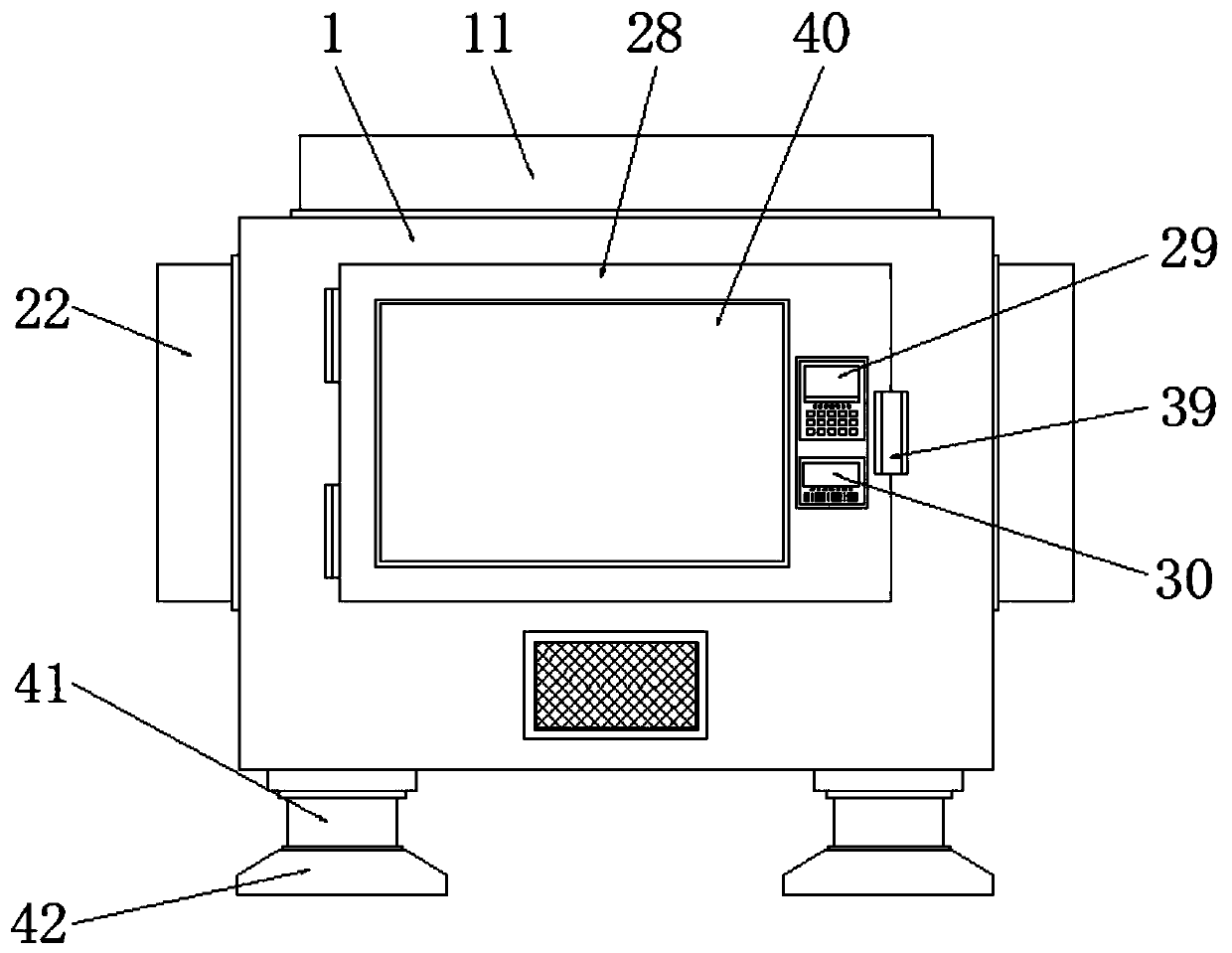
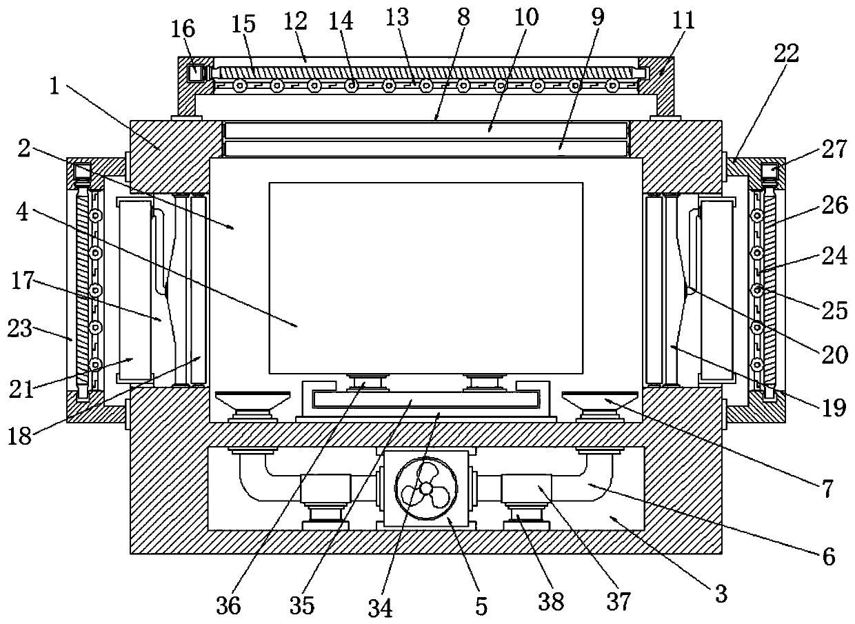
[0034] Embodiment one, such as Figure 1-7As shown, a 3D printer with a purification function according to an embodiment of the present invention includes a box body 1, and the interior of the box body 1 is provided with a placement cavity 2 and an installation cavity 3, and the interior of the placement cavity 2 is installed with 3D printer body 4, a fan-5 is installed inside the installation cavity 3, the fan-5 is a blower, and air duct-6 is installed on both sides of the fan-5, and the air duct One end of one 6 away from the fan one 5 runs through and extends to both sides of the bottom end of the placement cavity 2, the end of the air duct one 6 away from the fan one 5 is equipped with a windshield 7, and the box The top of the body 1 is provided with an opening one 8, and a filter plate one 9 and a filter plate two 10 are installed inside the opening one 8, through the fan one 5 and the wind cover 7 and the filter plate one 9 and The interaction between the two filter pl...

Embodiment 2

[0035] Embodiment two, such as figure 2 , 5 , 7, the end of the air duct 20 away from the fan 19 is connected to the top of the side of the purification chamber 21 close to the fan 19, and the interior of the purification chamber 21 is equipped with a connection pipe 31, and the top of the connecting pipe 31 communicates with the air pipe two 20; the top of the side of the purification chamber 21 away from the air pipe two 20 has an opening three 32, and the purification chamber 21 A baffle 33 is installed on the bottom of the opening three 32 and close to the side of the connecting pipe 31; when in use, the fan two 19 absorbs the toxic ultrafine particles in the box 1, and passes through The interaction between the air duct two 20 and the connecting pipe 31 is transported to the purification chamber 21, and the toxic ultrafine particles contained in the air are purified and filtered through the purification liquid in the purification chamber 21, and then passed through The...

Embodiment 3

[0036] Embodiment three, such as figure 2 As shown, a slot plate 34 is installed at the inner bottom end of the placement cavity 2, and a support plate 35 adapted to the groove of the slot plate 34 is installed inside the slot plate 34, and the support plate 35 The top of the top is symmetrically equipped with support blocks 36, and the tops of the support blocks 36 are all fixedly connected with the bottom end of the 3D printer body 4; the groove plate 34 is compatible with the support plate 35, and the support The plate 35 is clamped in the plate groove at the top of the groove plate 34. When in use, the 3D printer body 4 can slide on the top of the groove plate through the action of the support block 36, thereby facilitating People maintain and check the 3D printer body 4 , and at the same time, it is convenient to take out the 3D printed product after printing, which is convenient for people to use.


PUM


Abstract

Disclosed are a 3D printer having a purification function and a purification control system, the 3D printer comprising a box body. A placement cavity and an installation cavity are provided inside the box body; a 3D printer body is installed inside the placement cavity; a first fan is installed inside the installation cavity; first air ducts are installed on both sides of the first fan; the ends of the first air ducts away from the first fan penetrate and extend to two sides of the bottom end of the placement cavity; the end of each first air duct away from the first fan is provided with a hood; the top end of the box body is provided with an first opening; a first filter plate and a second filter plate are installed inside the first opening; a first hood body is installed at the top of the first opening; the top of the first hood body is provided with a first exhaust port; a plurality of first blades are installed inside the first exhaust port; a first gear is installed on one side of each first blade; a first threaded rod is installed on the top of each first gear; and a first motor is installed on one side of the first threaded rod.

Description

technical field [0001] The invention relates to the technical field of 3D printing, in particular, to a 3D printer with purification function and a purification control system. Background technique [0002] 3D printing is a kind of rapid prototyping technology. It is a technology based on digital model files and using bondable materials such as powdered metal or plastic to construct objects by layer-by-layer printing. 3D printing usually uses It is realized by a digital technology material printer; it is often used to manufacture models in the fields of mold manufacturing and industrial design, and is gradually used in the direct manufacture of some products. There are already parts printed using this technology; this technology is used in jewelry , footwear, industrial design, architecture, engineering and construction (AEC), automotive, aerospace, dental and medical industries, education, geographic information systems, civil engineering, firearms, and other fields; When ...

Claims


Application Information

Patent Timeline
Patent Type & Authority Patents(China)
IPC IPC(8): B29C64/30B33Y40/00B01D46/12B01D53/34B01D53/78
CPCB01D46/12B01D53/34B01D53/78B33Y40/00B29C64/30
Inventor 杨青雷芳娟
Owner 哈尔滨维森科技发展有限公司
Learn More