
Biological information measurement device and method, and program

A technology of human body information and measurement devices, which is applied in the fields of diagnostic recording/measurement, medical science, and diagnosis using light, etc. It can solve the problems of unrealistic use, large size of the device, and difficulty in improving the accuracy of measurement.

Inactive Publication Date: 2019-11-08
ORMON CORP +1
View PDF9 Cites 0 Cited by
  • Summary
  • Abstract
  • Description
  • Claims
  • Application Information

AI Technical Summary

Problems solved by technology

[0005] However, according to the blood pressure measurement device described in Japanese Patent Laid-Open Publication No. 2004-113368, the device size is large and it is difficult to improve the measurement accuracy.
In addition, since the premise is to use it in a specific environment and requires a specific person to operate, it is difficult to use it in daily diagnosis and at home
Moreover, there are many tubes and wires in the blood pressure measurement device, so it is unrealistic to use it in daily life and sleep.

Method used


Image

  • Biological information measurement device and method, and program
  • Biological information measurement device and method, and program
  • Biological information measurement device and method, and program

Examples


no. 1 approach

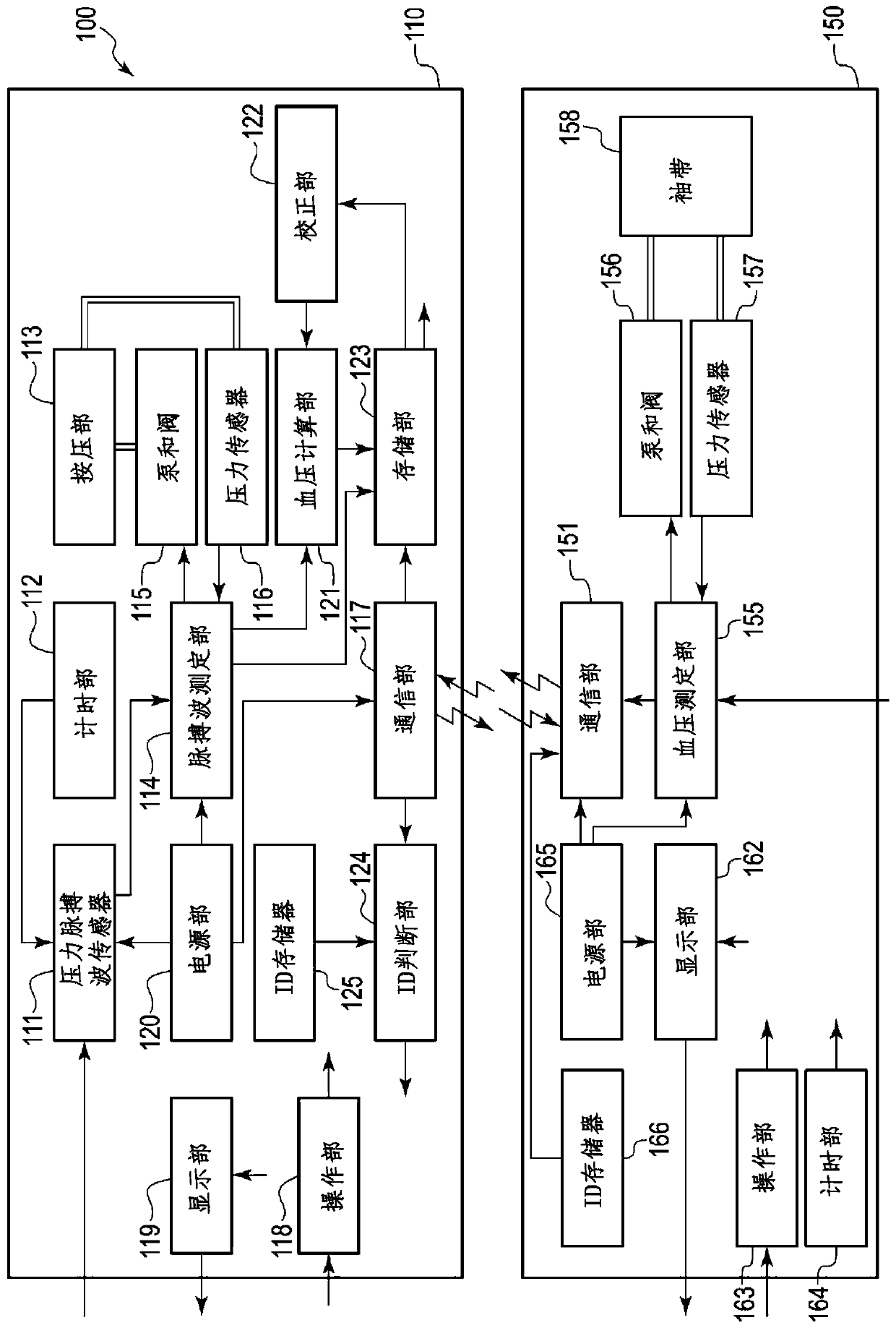
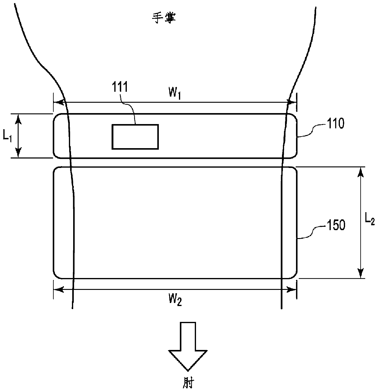
[0042] refer to figure 1 , figure 2 and image 3 The blood pressure measurement device 100 of this embodiment will be described. figure 1 It is a functional block diagram of the blood pressure measurement device 100, specifically showing the sensor device 110 and the calibration device 150. figure 2 It is a diagram showing an example of the blood pressure measuring device 100 worn on the wrist, and is a schematic perspective view seen from above the palm. The pressure pulse wave sensor 111 is arranged on the wrist side of the sensor device 110 . image 3 It is a schematic diagram of wearing the blood pressure measurement device 100, and it is a perspective schematic diagram of the palm viewed from the horizontal direction (the direction in which the fingers are arranged when the hand is opened). image 3 An example of the arrangement of the pressure pulse wave sensor 111 perpendicular to the radial artery is shown. image 3 It can be seen that the blood pressure measure...

no. 2 approach

[0088] refer to Figure 8 , figure 2 and image 3 The blood pressure measurement device 800 of this embodiment will be described. Figure 8 It is a functional block diagram of the blood pressure measurement device 800 , specifically showing the sensor device 810 and the calibration device 850 . figure 2It is a diagram showing an example of wearing the blood pressure measurement device 100 on the wrist, and is a schematic perspective view viewed from above the palm, and the same applies to the blood pressure measurement device 800 . The pressure pulse wave sensor 111 is arranged on the wrist side of the sensor device 110 . image 3 It is a schematic diagram of wearing the blood pressure measurement device 100, and it is a schematic perspective view of the palm viewed from the horizontal direction (the direction in which the fingers are arranged when the hand is opened), and the blood pressure measurement device 800 is the same. image 3 An example of the arrangement of th...

no. 3 approach

[0101] refer to Figure 11 , figure 2 and image 3 The blood pressure measurement device 1100 of this embodiment will be described. Figure 11 It is a functional block diagram of the blood pressure measurement device 1100 , specifically showing the sensor device 1110 and the calibration device 850 . figure 2 It is a diagram showing an example of the blood pressure measurement device 100 worn on the wrist, and is a schematic perspective view viewed from above the palm, and the same applies to the blood pressure measurement device 1100 . The pressure pulse wave sensor 111 is disposed on the wrist side of the sensor device 1110 . image 3 It is a schematic diagram of wearing the blood pressure measurement device 100 , and it is a schematic perspective view of the palm viewed from the horizontal direction (the direction in which the fingers are arranged when the hand is opened), and the blood pressure measurement device 1100 is the same. image 3 An example of the arrangemen...


PUM


Abstract

The present invention is worn continuously, and temporally successively acquires accurate information while calibrating biological information. Provided is a biological information measurement deviceequipped with a sensor device and a calibration device, wherein: the calibration device is equipped with a measurement unit for intermittently measuring first biological information, and a transmission unit for transmitting, to the sensor device, data including the first biological information, and calibration identification information which is identification information of the calibration device; and the sensor device is equipped with a reception unit for receiving the data and the calibration identification information, a determination unit for determining whether the calibration identification information is information for the calibration device which corresponds to the sensor device, a detection unit for temporally successively detecting pulse waves, and a calculation unit for, in cases in which the calibration identification information is information for the corresponding calibration device, calibrating the pulse waves using the first biological information and calculating second biological information from the calibrated pulse waves.

Description

technical field [0001] The present invention relates to a human body information measuring device, method and program for continuously measuring human body information. Background technique [0002] With the development of sensor technology, in an environment where high-performance sensors can be easily used, the importance of using human body information to detect changes in the human body at an early stage to assist in treatment has gradually increased in medical care. [0003] A human body information measurement device capable of measuring human body information such as pulse and blood pressure using information detected by the pressure sensor in a state where the pressure sensor is directly in contact with a body part through which an artery such as the radial artery of the wrist passes is known ( For example, refer to Japanese Patent Laid-Open Publication No. 2004-113368). [0004] In the blood pressure measurement device described in Japanese Patent Laid-Open Publica...

Claims


Application Information

Patent Timeline
Patent Type & Authority Applications(China)
IPC IPC(8): A61B5/022
CPCA61B5/0059A61B5/02116A61B5/02225A61B5/6824A61B5/6828A61B5/6829A61B2560/0238A61B2560/0271A61B2562/085A61B5/02241A61B5/0235
Inventor 北川毅山下新吾
Owner ORMON CORP
Learn More