Double-excitation double-fed mutual charging high-speed switched reluctance generator converter system

A reluctance generator and high-speed switch technology, which is applied in the direction of controlling the generator through the change of the magnetic field, controlling the generator, and the control system, can solve the problems of increasing labor or automatic maintenance costs, so as to improve charging efficiency and adaptability , the effect of improving efficiency and system benefit

Active Publication Date: 2020-11-27
浙江知多多网络科技有限公司
View PDF5 Cites 0 Cited by
  • Summary
  • Abstract
  • Description
  • Claims
  • Application Information

AI Technical Summary

Problems solved by technology

[0002] When the switched reluctance generator is running, according to the rotor position information, the working hours of each phase winding are divided into two stages: excitation and power generation, and they are carried out in time. The excitation stage greatly affects the subsequent power generation capacity. The excitation power supply is very important. The changing excitation power supply can Enhance the adaptability and flexibility of the system, and even contribute to the improvement of power generation capacity. In the case of using batteries as the excitation power supply, there is often a major problem that the excitation voltage is fixed at a value, not to mention the enhanced excitation capacity that the industry often expects However, the use of different battery-powered excitations enhances flexibility, but greatly increases the cost of manual or automatic maintenance

Method used


Image

  • Double-excitation double-fed mutual charging high-speed switched reluctance generator converter system

Examples


Embodiment Construction

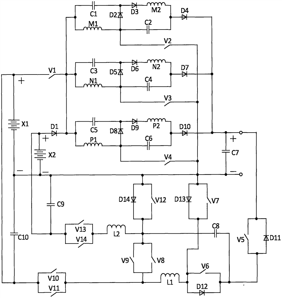
[0033] In this embodiment, the double-excitation double-fed mutual charging high-speed switched reluctance generator converter system, the circuit structure of the converter system is as follows figure 1 As shown, it consists of the first storage battery X1, the second storage battery X2, the first switching tube V1, the second switching tube V2, the third switching tube V3, the fourth switching tube V4, the fifth switching tube V5, and the sixth switching tube V6 , the seventh switch tube V7, the eighth switch tube V8, the ninth switch tube V9, the tenth switch tube V10, the eleventh switch tube V11, the twelfth switch tube V12, the thirteenth switch tube V13, and the fourteenth switch tube Tube V14, first diode D1, second diode D2, third diode D3, fourth diode D4, fifth diode D5, sixth diode D6, seventh diode D7, eighth diode D8, ninth diode D9, tenth diode D10, eleventh diode D11, twelfth diode D12, thirteenth diode D13, fourteenth diode Diode D14, the first winding M1 of ...


PUM


Abstract

A double-excitation double-feed mutual-charging high-speed switched reluctance generator converter system is composed of two storage batteries, fourteen switch tubes, fourteen diodes, a three-phase winding, ten capacitors and two inductors. A phase winding converter loop divides each phase winding into two parts for respective excitation, so that the reliability is enhanced, the excitation effectis enhanced, and the output power generation voltage is directly far higher than the voltage of an input side storage battery by utilizing the same phase winding converter loop, i.e., the voltage is directly boosted; due to the arrangement of the double storage batteries, the problem that an excitation power supply cannot be selected under the excitation of the storage batteries is solved, meanwhile, a series of problems of automatic charging, reverse energy feedback, automatic charging between the double storage batteries and the like of the storage batteries are intensively solved through aset of converter circuit and regulation and control of the converter circuit, and the adaptability and flexibility of the system are improved; an isolation link of the whole system structure is also omitted; the converter system is suitable for being applied to the field of small and medium-power high-speed switched reluctance generator systems with output in connection with independent loads or grid connection under driving of various kinds of power.

Description

technical field [0001] The invention relates to the field of switched reluctance motor systems, in particular to a high-speed switched reluctance generator converter system with dual-voltage excitation power supply, double-fed energy output, automatic charging of the excitation power supply and mutual charging to directly increase the output voltage and its control method . Background technique [0002] When the switched reluctance generator is running, according to the rotor position information, the working hours of each phase winding are divided into two stages: excitation and power generation, and they are carried out in time. The excitation stage greatly affects the subsequent power generation capacity. The excitation power supply is very important. The changing excitation power supply can Enhance the adaptability and flexibility of the system, and even contribute to the improvement of power generation capacity. In the case of using batteries as the excitation power sup...

Claims


Application Information

Patent Timeline
Patent Type & Authority Patents(China)
IPC IPC(8): H02P9/30
CPCH02P9/307
Inventor 孙冠群金尔崇陈卫民
Owner 浙江知多多网络科技有限公司
Why Eureka
Try Eureka