A Method for Reducing Circumferential Temperature Difference Between Motor Coil and Iron Core
A technology of iron core circumference and coil, which is applied in the field of reducing the circumferential temperature difference between the motor coil and the iron core, can solve the problems that the circumferential uniformity of the airflow cannot be effectively improved, the wind speed can not be uniformly distributed in the circumferential direction, and the circumferential temperature difference of the motor cannot be effectively reduced. Achieve good and uniform heat dissipation effect, ensure uniform heat dissipation effect, and realize uniform distribution of wind speed in the circumferential direction
- Summary
- Abstract
- Description
- Claims
- Application Information
AI Technical Summary
Problems solved by technology
Method used
Image
Examples
Embodiment 1
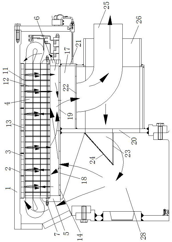
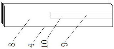
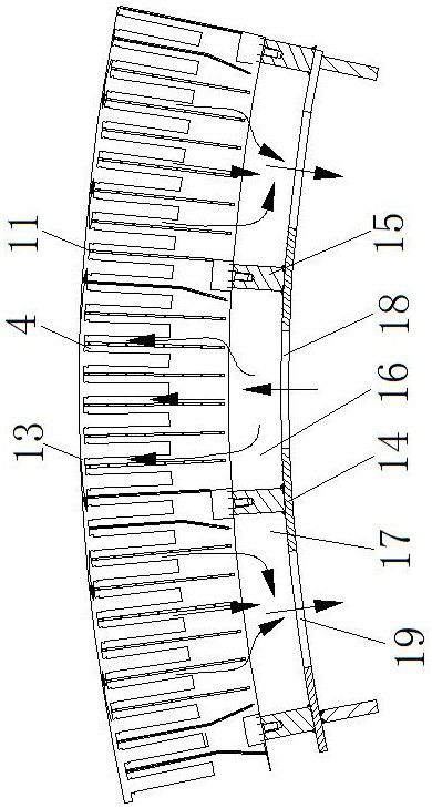
[0037] see Figure 1-Figure 5 , a method for reducing the circumferential temperature difference between a motor coil and an iron core, comprising the following steps:
[0038] a. Install the device for reducing the circumferential temperature difference between the large-diameter motor coil and the iron core on the wind turbine;
[0039] b. Install an oblique windshield 24 at the outlet of the air inlet pipe 26, the angle between the oblique windshield 24 and the first vertical plate 20 is 30°, and install an air volume adjustment plate 27 on the air inlet 18 , the air volume regulating plate 27 is hinged to the first circumferential ring plate 14, and the air circumferential resistance is adjusted through the air volume regulating plate 27;
[0040] c. In a circumferentially symmetrical unit, the wind passage area 29 near the fan axis is the smallest, and the wind passage area 29 at the far fan end away from the fan axis is the largest.
[0041] "a. Install the device to r...
Embodiment 2
[0043] see Figure 1-Figure 5 , a method for reducing the circumferential temperature difference between a motor coil and an iron core, comprising the following steps:
[0044] a. Install the device for reducing the circumferential temperature difference between the large-diameter motor coil and the iron core on the wind turbine;
[0045] b. Install an inclined windshield 24 at the outlet of the air inlet pipe 26, the angle between the inclined windshield 24 and the first vertical plate 20 is 45°, and install an air volume regulating plate 27 on the air inlet 18 , the air volume regulating plate 27 is hinged to the first circumferential ring plate 14, and the air circumferential resistance is adjusted through the air volume regulating plate 27;
[0046] c. In a circumferentially symmetrical unit, the wind passage area 29 near the fan axis is the smallest, and the wind passage area 29 at the far fan end away from the fan axis is the largest.
[0047] The device for reducing t...
Embodiment 3
[0050] see Figure 1-Figure 5 , a method for reducing the circumferential temperature difference between a motor coil and an iron core, comprising the following steps:
[0051] a. Install the device for reducing the circumferential temperature difference between the large-diameter motor coil and the iron core on the wind turbine;
[0052] b. Install an oblique windshield 24 at the outlet of the air inlet pipe 26, the angle between the oblique windshield 24 and the first vertical plate 20 is 60°, and install an air volume adjustment plate 27 on the air inlet 18 , the air volume regulating plate 27 is hinged to the first circumferential ring plate 14, and the air circumferential resistance is adjusted through the air volume regulating plate 27;
[0053] c. In a circumferentially symmetrical unit, the wind passage area 29 near the fan axis is the smallest, and the wind passage area 29 at the far fan end away from the fan axis is the largest.
[0054] The device for reducing the...
PUM
 Abstract
Description
Claims
Application Information
 - R&D
- Intellectual Property
- Life Sciences
- Materials
- Tech Scout
- Unparalleled Data Quality
- Higher Quality Content
- 60% Fewer Hallucinations
Browse by: Latest US Patents, China's latest patents, Technical Efficacy Thesaurus, Application Domain, Technology Topic, Popular Technical Reports.
© 2025 PatSnap. All rights reserved.Legal|Privacy policy|Modern Slavery Act Transparency Statement|Sitemap|About US| Contact US: help@patsnap.com


