Anti-seismic bracket with bump damping adjusting function
An anti-vibration support, shock absorption and damping technology, applied in the direction of pipes/pipe joints/fittings, mechanical equipment, pipe components, etc., to achieve the effect of easy operation, various adjustment methods, and prevention of hard damage
- Summary
- Abstract
- Description
- Claims
- Application Information
AI Technical Summary
Problems solved by technology
Method used
Image
Examples
Embodiment 1
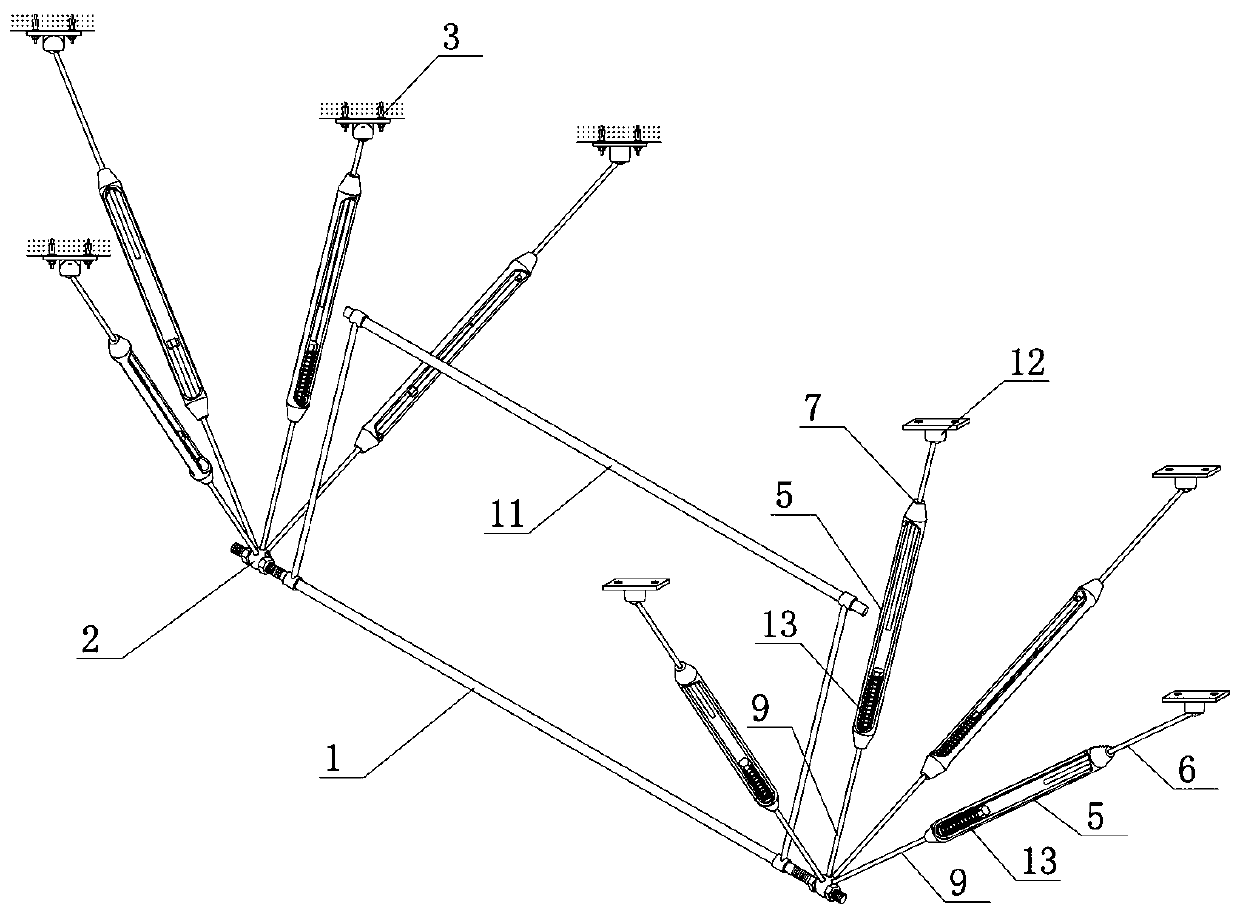
[0037] Embodiment 1: The first kind of shock-absorbing and damping adjustment anti-seismic support, such as figure 1 As shown, the anti-seismic bracket supports the beam 1 and the auxiliary beam 11, and auxiliary fixing parts can also be provided between the support beam 1 and the auxiliary beam 11, for example, a fixing collar is installed on the support beam 1 to fix the circular pipe assembly. When the supporting beam and the auxiliary beam are used, the square conveying pipeline can be clamped and fixed. The two ends of the supporting beam or the auxiliary beam are traction ends 2 for connecting traction components.
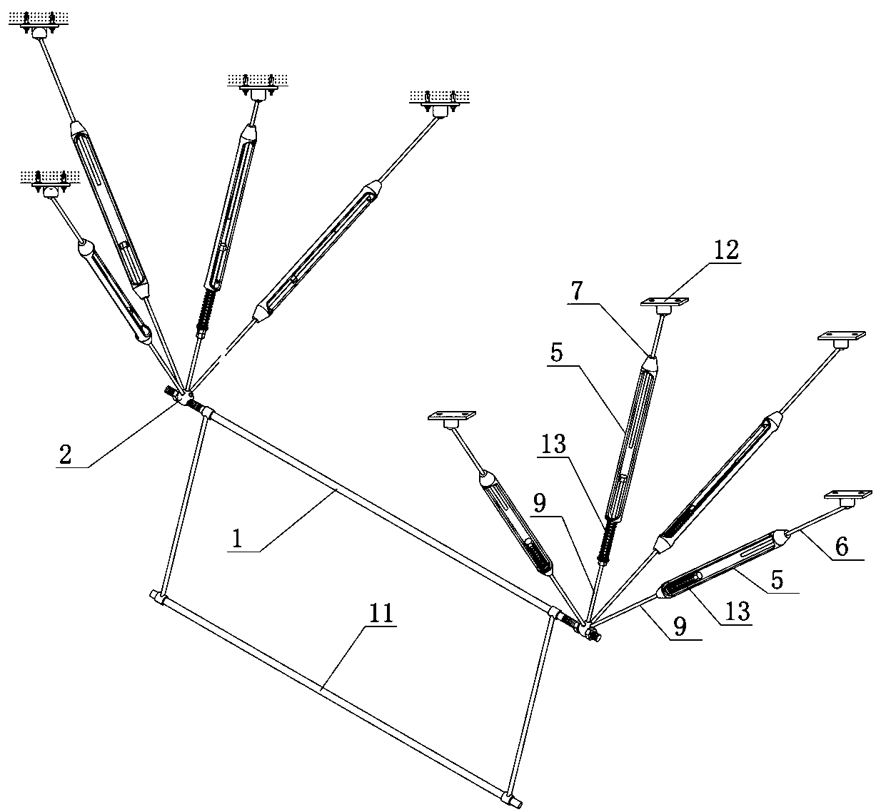
[0038] In this example, see Figure 2-Figure 4 , located on each traction end 2 at both ends of the supporting beam 1, a traction component is connected upwards along the center, the upper end of the traction component is connected to the ceiling, usually an expansion sleeve is installed after the ceiling is drilled, and the upper end of the mandrel is conne...
Embodiment 2
[0042] Embodiment 2: The second kind of shock-absorbing and damping-adjusting anti-seismic support, such as figure 2 As shown, the anti-seismic support includes at least one supporting beam 1, and an auxiliary beam 11 can also be connected in parallel under the supporting beam, and a fixing collar is installed on the individual supporting beam to fix the circular pipe assembly, and the supporting beam and the auxiliary beam are used simultaneously It can be clamped and fixed to the square conveying pipeline. The two ends of the supporting beam or the auxiliary beam are traction ends 2 for connecting traction components.
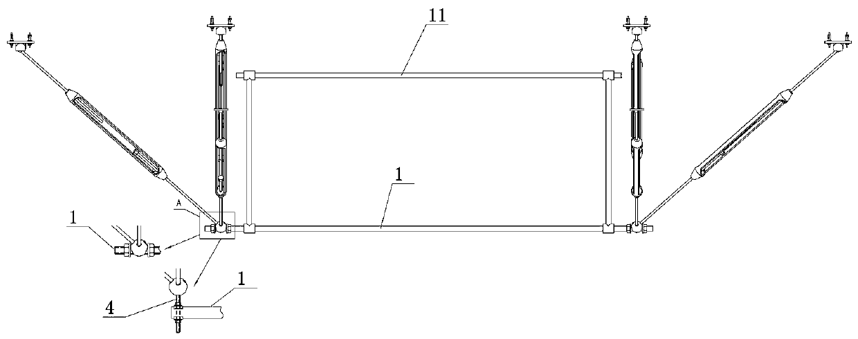
[0043] In this example, see figure 1 , image 3 and Figure 4 , located on each traction end 2 at both ends of the supporting beam 1, a jack rod assembly is connected upwards along the center, the upper end of the jack rod assembly is connected to the ceiling, usually an expansion sleeve is installed after the ceiling is drilled, and the jack rod is conne...
Embodiment 3
[0047] Embodiment 3: The third shock-absorbing and damping-adjusting anti-seismic bracket is based on Embodiment 1, and is a symmetrical traction member along the left and right sides of the ejector rod assembly, and its lower end is longitudinally hinged to the corresponding hinge of the traction end 2 through a pin shaft. On the connecting head 4, its upper end is vertically hinged to the movable connection seat by a pin shaft. The lower end of the traction part directly behind the push rod assembly is horizontally hinged on the corresponding hinge joint of the traction end 2 through the pin shaft, and its upper end is horizontally hinged to the movable connection seat through the pin shaft.
PUM
 Abstract
Description
Claims
Application Information
 - R&D
- Intellectual Property
- Life Sciences
- Materials
- Tech Scout
- Unparalleled Data Quality
- Higher Quality Content
- 60% Fewer Hallucinations
Browse by: Latest US Patents, China's latest patents, Technical Efficacy Thesaurus, Application Domain, Technology Topic, Popular Technical Reports.
© 2025 PatSnap. All rights reserved.Legal|Privacy policy|Modern Slavery Act Transparency Statement|Sitemap|About US| Contact US: help@patsnap.com


