
Laser micro structure machining method

A processing method and laser processing technology, which is applied in laser welding equipment, metal processing equipment, manufacturing tools, etc., can solve the problems of difficulty in guaranteeing processing quality, low coordination, and poor visibility of processing effects, etc., to improve control synchronization, Improve process complexity and improve effects that are difficult to observe

Active Publication Date: 2019-11-08
NANTONG UNIVERSITY
View PDF6 Cites 5 Cited by
  • Summary
  • Abstract
  • Description
  • Claims
  • Application Information

AI Technical Summary

Problems solved by technology

[0003] The current laser microtexture processing methods mostly rely on the control scheme of the existing CNC machine tool system. However, the control method of the traditional CNC machine tool system is often closed within the system framework. The control method is cumbersome and bloated, and the openness is low. For example, on a multi-axis machine tool equipped with high-performance lasers, laser micro-texture processing of workpieces with various shapes requires the design of special processing methods for laser micro-texture processing requirements.
[0004] At present, the laser micro-texture processing method still has the following shortcomings or deficiencies: (1) The movement accuracy of the machine tool is low, which cannot meet the high-precision requirements of laser micro-texture processing; (2) The openness of the control method based on the existing CNC machine tool system Low cost, cumbersome operation, machine tool motion G code needs to be manually written by the operator, and the efficiency is low; (3) The selection of processing technology is scarce, and the visibility of the processing effect is poor, which cannot meet the processing requirements of various workpiece shapes and textures, and cannot be real-time Monitor processing progress
(4) The coordination between laser and machine tool linkage control is low, the positioning accuracy is low, and the processing quality is difficult to guarantee

Method used


Image

  • Laser micro structure machining method
  • Laser micro structure machining method
  • Laser micro structure machining method

Examples


Embodiment Construction

[0032] In order to make the purpose, technical solutions and advantages of the embodiments of the present invention clearer, the technical solutions in the embodiments of the present invention will be clearly and completely described below. Obviously, the described embodiments are part of the embodiments of the present invention, not all of them. the embodiment. Elements and features described in one embodiment of the present invention may be combined with elements and features shown in one or more other embodiments. It should be noted that representation and description of components and processes that are not related to the present invention and that are known to those of ordinary skill in the art are omitted from the description for the purpose of clarity. Based on the embodiments of the present invention, all other embodiments obtained by persons of ordinary skill in the art without making creative efforts belong to the protection scope of the present invention.

[0033] ...


PUM


Abstract

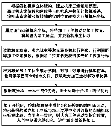
The invention discloses a laser micro structure machining method. The laser micro structure machining method includes the following steps that a three-dimensional movement model of a machine tool is built, the real-time positions of a linear shaft and a rotating shaft of the machine tool are converted into machining machine tool coordinates; a to-be-machined workpiece is moved to a machining position, the machining position is set to be a machining original point, and a machine tool coordinate system is updated; machining position parameters are read, and laser machining position coordinates are calculated and obtained; according to the coordinates, a machining schematic diaphragm is calculated and generated, and analog simulation is performed on the machining effect; G codes are generatedaccording to the coordinates, and used for path planning of a movement platform in machining; and a controller controls a machining machine tool to move according to the G codes, the obtained laser machining coordinates and machining machine tool coordinates read in real time in the machining process are compared, when the obtained laser machining coordinates and the machining machine tool coordinates read in real time in the machining process are consistent, it is considered that the workpiece moves to an assigned position, and therefore a laser device is controlled to emit out light, and laser micro structure machining is performed. The laser micro structure machining method can achieve high precision machining, improves the control synchronism of the laser device and machine tool movement, and effectively improves the laser micro structure morphology observing difficulty.

Description

technical field [0001] The invention relates to the fields of laser micro-texture processing technology, machine tool processing technology and automatic control technology, in particular to a laser micro-texture processing method. Background technique [0002] Laser surface microtexture refers to a surface treatment process that ablates and gasifies the surface of a material with a laser to form a texture of a certain shape. It has research prospect and application value. With the continuous development of laser technology, laser microtexture research is developing towards refinement, complexity, and diversification. While continuously improving the intelligent level of laser microtexture processing systems, laser microtexture processing methods are also being developed. put forward higher requirements. [0003] The current laser microtexture processing methods mostly rely on the control scheme of the existing CNC machine tool system. However, the control method of the tr...

Claims


Application Information

Patent Timeline
Patent Type & Authority Applications(China)
IPC IPC(8): B23K26/352B23K26/08
CPCB23K26/0853B23K26/0869B23K26/355
Inventor 吴国庆王矾张旭东姚建南朱维南胡祖辉刘文杰
Owner NANTONG UNIVERSITY
Learn More