
Unified control method for electric and power generation running states of brushless DC motor

A brushless DC motor and operating state technology is applied in the field of switching control of the operating state of a brushless DC motor, which can solve the problems of unstable speed and poor smoothness, and achieve the effect of smooth transition.

Active Publication Date: 2019-11-05
NORTHWESTERN POLYTECHNICAL UNIV
View PDF4 Cites 1 Cited by
  • Summary
  • Abstract
  • Description
  • Claims
  • Application Information

AI Technical Summary

Problems solved by technology

It overcomes the problems of unstable speed and poor smoothness caused by the forced hard switching of the commutation logic in the traditional electric and power generation states

Method used


Image

  • Unified control method for electric and power generation running states of brushless DC motor
  • Unified control method for electric and power generation running states of brushless DC motor
  • Unified control method for electric and power generation running states of brushless DC motor

Examples


Embodiment Construction

[0044] Now in conjunction with embodiment, accompanying drawing, the present invention will be further described:

[0045] The specific implementation steps are as follows:

[0046] Step 1: In the DSP control program of the brushless DC motor, modify the settings of the ePWM control module so that it outputs two complementary PWM signals with dead zones:

[0047] 1. Modify the action limit sub-module of the ePWM control module

[0048] EPwm1Regs.AQCTLB.bit.ZRO=AQ_SET;

[0049] EPwm1Regs.AQCTLB.bit.CBU=AQ_CLEAR;

[0050] 2. Modify the dead zone control of the ePWM control module

[0051] EPwm1Regs.DBCTL.bit.OUT_MODE = DB_FULL_ENABLE;

[0052] EPwm1Regs.DBCTL.bit.POLSEL = DB_ACTV_HIC;

[0053] EPwm1Regs.DBRED=100;

[0054] EPwm1Regs.DBFED=100;

[0055] 3. Modify the output control of the ePWM control module

[0056] GpioCtrlRegs.GPAMUX1.bit.GPIO0=1;

[0057] GpioCtrlRegs.GPAMUX1.bit.GPIO1=1;

[0058] GpioCtrlRegs.GPAPUD.bit.GPIO0=0;

[0059] GpioCtrlRegs.GPAPUD.bit.GPIO...


PUM


Abstract

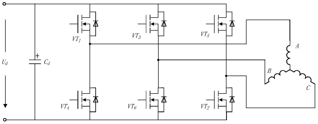
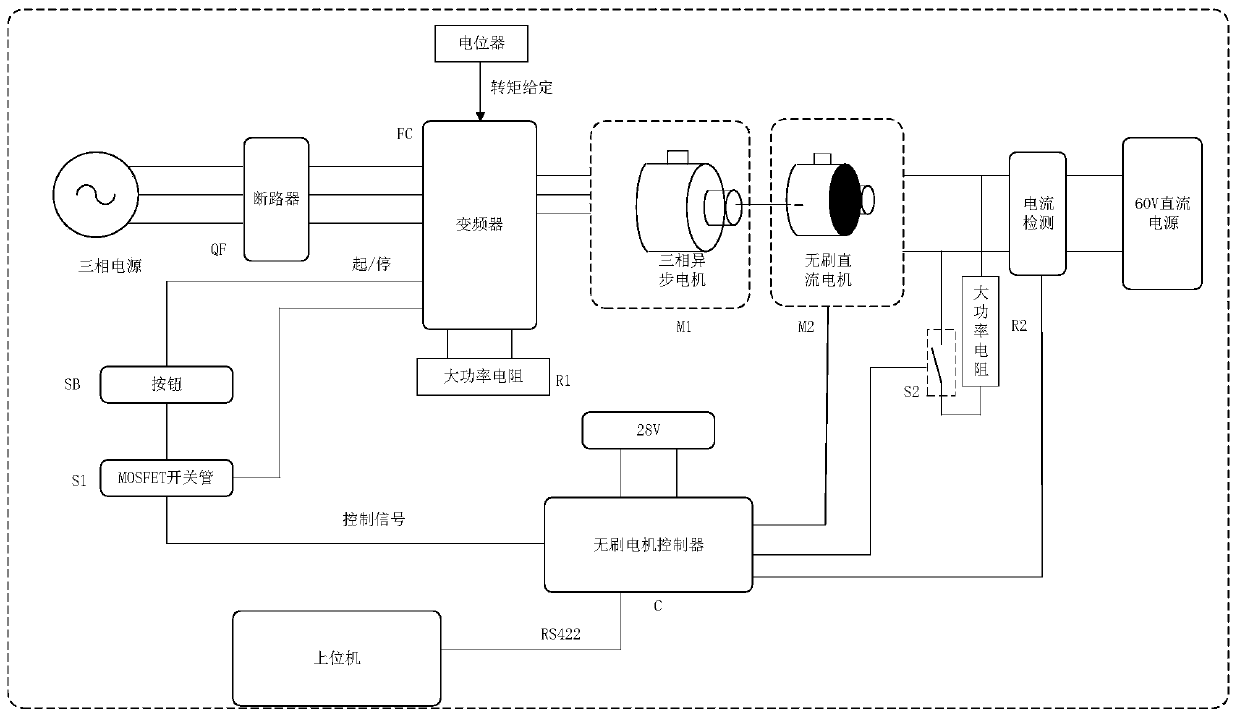
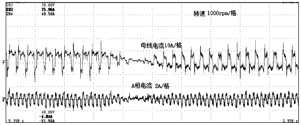
The invention relates to a unified control method for electric and power generation running states of a brushless DC motor. The unified control method can be realized in a brushless DC motor system controlled under a DSP+CPLD architecture. A CPLD serves as a peripheral and is connected with a DSP through a data bus address bus and a control bus which are parallel to each other. The DSP is responsible for changing the duty ratio in real time according to a control algorithm, forming complementary PWM signals and sending the signals to the CPLD. The CPLD performs the logical operation with the complementary PWM signals sent by the DSP according to the Hall position signal of the brushless DC motor to form a driving signal to control the main power circuit of the brushless DC motor, so that the stability and control of the rotating speed of the motor are realized. In the control system, a bipolar modulation method is adopted, driving signals with opposite phases and dead zones are appliedto an upper switching tube and a lower switching tube of the same bridge arm, and therefore, the unified commutation logic can be achieved. When the motor is switched between an electric state and apower generation state, the working state of the motor does not need to be judged, and the commutation logic does not need to be changed.

Description

technical field [0001] The invention belongs to the conversion control of the running state of a brushless direct current motor, and relates to a unified control method for the two running states of the brushless direct current motor, electric and power generation, in particular to a control method for the smooth transition of the electric and power generation of the brushless direct current motor. Background technique [0002] When an electric vehicle is directly driven by a permanent magnet brushless DC motor, if it runs in constant speed cruise mode and encounters a downhill road condition, an external torque will be superimposed on the output shaft of the motor in a positive direction, that is, a parallel load will appear, which will cause the motor to continuously Acceleration, and the closed-loop function of cruise control often controls the motor to run at a steady speed, so braking is required to keep the vehicle moving forward at a constant speed. During the braking...

Claims


Application Information

Patent Timeline
IPC IPC(8): H02P7/29
CPCH02P7/29
Inventor 马瑞卿樊平张煜辰党智乾
Owner NORTHWESTERN POLYTECHNICAL UNIV
Learn More