
A Semi-coaxial Microstrip Combination RF Transmission Line Structure

A coaxial transmission line, radio frequency transmission technology, applied in the field of radio frequency microwave, can solve the problems of "probe" breakage, weakened structural strength, and small "probe" diameter, and achieves low assembly and disassembly operation difficulty, reliability and high reliability. The effect of improved stability and easy batch processing

Active Publication Date: 2021-08-06
THE 724TH RES INST OF CHINA SHIPBUILDING IND
View PDF7 Cites 0 Cited by
  • Summary
  • Abstract
  • Description
  • Claims
  • Application Information

AI Technical Summary

Problems solved by technology

This paper presents an overall solution for coaxial-microstrip-coaxial connection, which has a narrow scope of application, and has many parts and high implementation cost.
In particular, the indium sheet is thin and weak, lacks positioning in the structure, and requires high assembly operations
[0005] The defects of the existing design are: 1) When soldering is used, the "probe" and the microstrip line are rigidly connected. "pin" breakage, the risk of peeling of solder joints or peeling of copper and substrate
2) The "probe" of the coaxial inner core protrudes separately and has been cut. As the operating frequency increases, the diameter of the "probe" becomes smaller, the structural strength is weakened, and it is easily damaged during assembly and disassembly
Patent (CN 206003942 U) Although the "probe" has not been cut, and the indium sheet is used as the transition from the "probe" to the microstrip, damage to the indium sheet cannot be avoided during disassembly

Method used


Image

  • A Semi-coaxial Microstrip Combination RF Transmission Line Structure
  • A Semi-coaxial Microstrip Combination RF Transmission Line Structure
  • A Semi-coaxial Microstrip Combination RF Transmission Line Structure

Examples


Embodiment 1

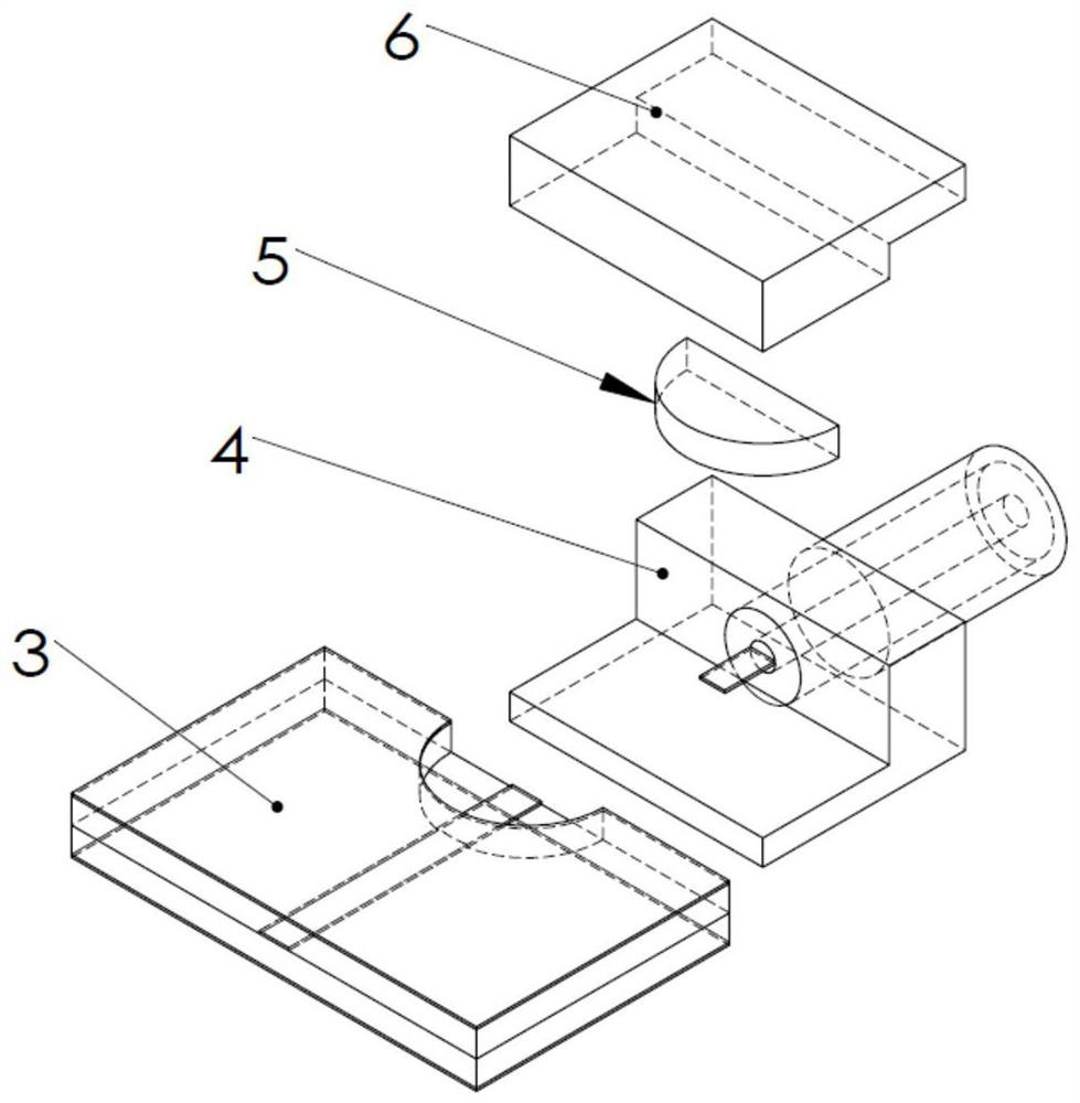
[0034] Implementation example 1: see Figure 6 , this example provides a design solution for a horizontal crimping RF connector installed on a microstrip line, including three parts: the microstrip line 1 to be installed, the microstrip crimping connector 17 and the metal pressing block 6 . The coaxial inner diameter of the microstrip crimp connector 17 is 1 mm, the coaxial medium is polytetrafluoroethylene, the dielectric constant is 2.08, and the outer diameter is 3.3 mm when the calculated characteristic impedance is 50 ohms. Extend half of the coaxial conductor, medium and outer conductor by 5 mm through the axis in the horizontal direction to obtain a semi-coaxial 7. The substrate thickness of the microstrip line 1 is 1 mm, the dielectric constant is 2.55, and the width of the microstrip line corresponding to a calculated characteristic impedance of 50 ohms is 2.8 mm. The matching microstrip 8 is located at the end of the microstrip line 1 and has the same length as the ...

Embodiment 2

[0035] Implementation example 2: change and obtain on the basis of example 1, refer to Figure 7 . The medium of the stripline 3 is formed by gluing two substrates together, with a total thickness of 2.1 mm and a dielectric constant of 2.55. The calculated characteristic impedance is 50 ohms and the corresponding center conduction strip width is 1.46 mm. A 5mm×5mm groove is opened at the end to expose the central conduction band, corresponding to a substrate thickness of 1mm, and the width of the central conduction band line of the matching microstrip 8 determined from Example 1 when the characteristic impedance is 50 ohms is 1.24mm. Cut the semi-coaxial 7 part of the ribbon crimp connector 22 into a step of 5 mm x 5 mm with a height of 1.1 mm, and the outer conductor of the part below the step extends outward by 2 mm. During assembly, under the action of the metal pressing block 6, the lower ground layer forms a continuous grounding plane with the outer conductor and the ext...


PUM


Abstract

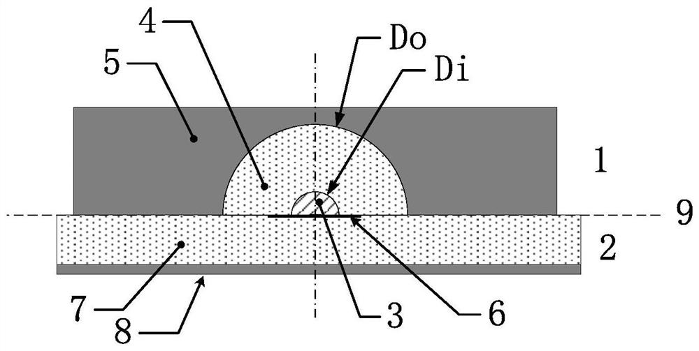
The invention discloses a semi-coaxial microstrip combined radio frequency transmission line structure, which belongs to the technical field of radio frequencies and microwaves, and includes semi-coaxial and matching microstrips. The semi-coaxial includes an outer conductor, a semi-circular dielectric and a semi-circular inner conductor, and the three form a unified installation contact surface; the matching microstrip includes a substrate on which a central conductive strip and a grounding metal layer are carried. In the working state, the semi-coaxial is pressed on the upper surface of the matching microstrip, and the center lines are aligned. Under the action of the upper and lower pressures, the semi-circular inner conductor and the central conduction band are attached to form a central conductor. The semi-coaxial outer conductor is On the upper ground layer, the electromagnetic wave is transmitted in TEM mode in the carrier composed of the semi-ring medium and the substrate. The invention is applied to the structural transition of the radio frequency connector from the coaxial to the microstrip line (strip line), and is especially suitable for the design of the horizontal crimping type radio frequency connector.

Description

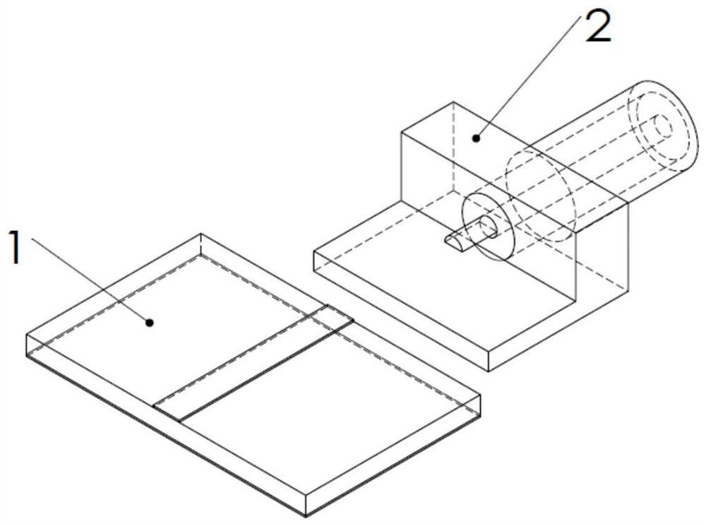
technical field [0001] The invention belongs to the field of radio frequency microwave technology. Background technique [0002] In existing horizontally installed RF connectors, the coaxial line is directly transitioned to the microstrip line (strip line), and the interface adopts a single interface perpendicular to the transmission direction. Since the central conduction band of the microstrip line is thin copper, the structural strength is poor, and in order to reduce the influence of transmission mismatch on the electrical performance, the axis of the coaxial line should be as close as possible to the central conduction band of the microstrip line. The inner core of the shaft is protruded and appropriately reduced into a "probe", and then connected with the central guide belt. There are two specific implementations: [0003] 1) When connecting with the microstrip line, refer to the attached figure 1 , the "probe" is semicircular, the microstrip line 1 is inserted betw...

Claims


Application Information

Patent Timeline
Patent Type & Authority Patents(China)
IPC IPC(8): H01P3/02H01P3/04H01P3/06
CPCH01P3/02H01P3/04H01P3/06
Inventor 朱平丛友记卢青黄彩华
Owner THE 724TH RES INST OF CHINA SHIPBUILDING IND
Learn More