


Quick Research
Generate reliable direction feasibility study reports for your R&D in just a few steps.

Technical Q&A
Discover and master advanced knowledge NOW. Basics, ideas, possibilities, all at once.

Find Solutions
As an expert in R&D theories, this can generate solutions to your technical problems instantly.

Evaluate Feasibility
Analyze your overall solution with one click, know your potential R&D risks in advance.

Monitor Landscape
Get weekly tech updates, stay abreast of the latest tech innovations and key insights.
Transformer insulation sheath
A technology for insulating sheaths and transformers, applied in the direction of insulators, insulators, transformer/inductor parts, etc., can solve the problems of inconvenient maintenance, inability of insulating sheaths to apply to terminals, and low service life, so as to achieve convenient maintenance, The effect of improving the safety of use and increasing the service life
- Summary
- Abstract
- Description
- Claims
- Application Information
AI Technical Summary
Problems solved by technology
Method used
Image

Examples
Embodiment 1
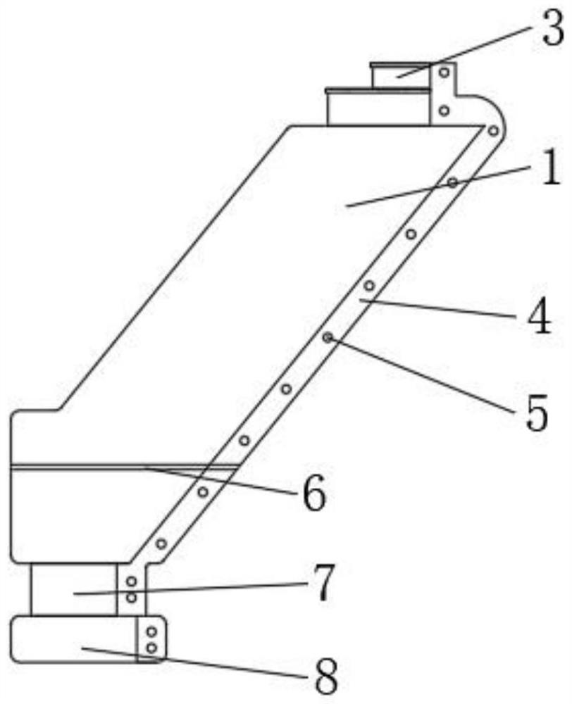
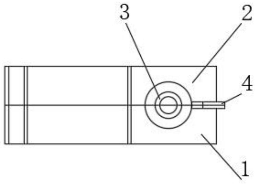
[0028] Such as figure 1 , 2 As shown in . There is a fixed bead 4, the side of the fixed bead 4 is fitted with a fixed plastic nail 5, the sides of the first sheath shell 1 and the second sheath shell 2 are provided with a bending bar 6, the first sheath shell 1 and the second sheath shell 2 The bottom surface of the second sheath shell 2 is provided with a wire jacket shell 7, the bottom surface of the wire jacket shell 7 is provided with a fixed sleeve shell 8, and the top surfaces of the first sheath shell 1 and the second sheath shell 2 are provided with The outlet casing 3, the terminal of the transformer is protected between the first sheath casing 1 and the second sheath casing 2, and is fixed on the bottom of the connection terminal through the fixed casing 8, and the cable is connected from the outlet casing 3 The top surface of the outlet casing 3 is provided with an outlet sleeve reinforcing ring, which can be changed to the side reinforcement rib of the outlet ca...
Embodiment 2
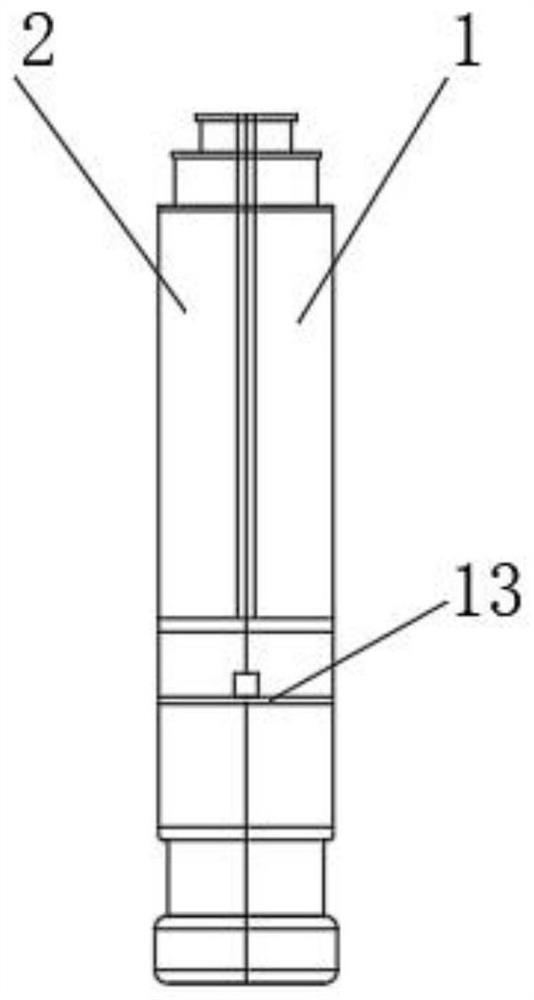
[0030] Such as figure 2 , 3 , 4, and 5, the embodiment of the present invention provides a transformer insulating sheath, the side of the first sheath shell 1 close to the second sheath shell 2 and the side of the outlet sheath 3 are provided with connecting sleeves 9, the second A sheath shell 1 is provided with a waterproof slot 10 near the side of the second sheath shell 2, and the waterproof slot 10 is arranged at an end away from the fixed bead 4, and the bottom surface of the waterproof slot 10 is higher than the bending bar 6 The top surface of the top surface, the connecting sleeve 9 is arranged along the arc on the side of the first sheath shell 1, and the cable can be pinned by the arc design to prevent the connection between the cable and the terminal from being loosened due to accidental pulling. The connecting sleeves 9 are arranged in a straight line, but they cannot play the role of pinning the cables, and the protective performance of the insulating sheath wi...
PUM
 Abstract
Description
Claims
Application Information
 - R&D Engineer
- R&D Manager
- IP Professional
- Industry Leading Data Capabilities
- Powerful AI technology
- Patent DNA Extraction
Browse by: Latest US Patents, China's latest patents, Technical Efficacy Thesaurus, Application Domain, Technology Topic, Popular Technical Reports.
© 2024 PatSnap. All rights reserved.Legal|Privacy policy|Modern Slavery Act Transparency Statement|Sitemap|About US| Contact US: help@patsnap.com