
Server room temperature field detection method and system

A server cabinet and server technology, which is applied in the detection field, can solve the problems that it is difficult to know the abnormal temperature of the server in the cabinet, the cabinet is large, and the temperature distribution of the computer room cannot be known.

Inactive Publication Date: 2019-11-05
广东优世联合控股集团股份有限公司
View PDF0 Cites 5 Cited by
  • Summary
  • Abstract
  • Description
  • Claims
  • Application Information

AI Technical Summary

Problems solved by technology

[0004] However, the space of the general computer room is large, the cabinets in the computer room are large in size, and the number of cabinets is large. Only relying on the air flow generated by the air conditioner, there are still problems of uneven temperature distribution in the computer room, such as: the temperature difference between the upper and lower layers of the cabinet, and dense cabinets. The temperature difference between the office and the remote place, etc., the temperature detection at a specific point can only collect the temperature information in this area, but it cannot understand the overall temperature distribution of the computer room, and it is not easy to know the abnormal temperature of the servers in the cabinet.

Method used


Image

  • Server room temperature field detection method and system
  • Server room temperature field detection method and system
  • Server room temperature field detection method and system

Examples


Embodiment 1

[0035] In the embodiment of the method for detecting the temperature field in the server room of the present invention, the schematic flow chart of the method for detecting the temperature field in the server room is as follows figure 1 shown. figure 1 Among them, the temperature field detection method of the server room includes the following steps:

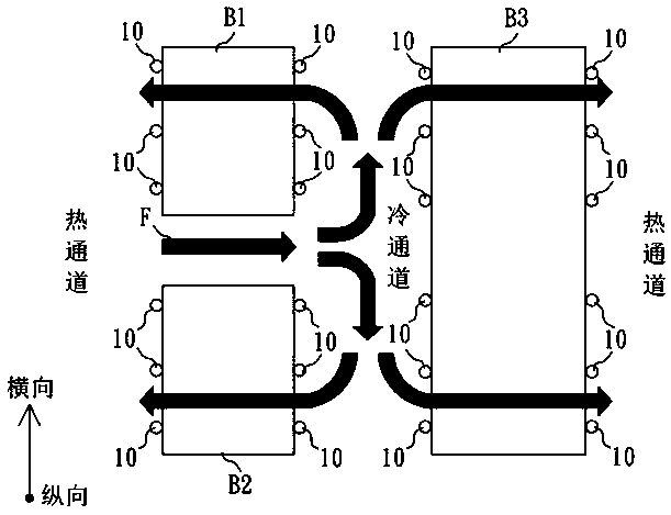
[0036] The temperature field detection step is to detect and collect the temperatures of the cold side and the hot side of each server cabinet in the computer room, and generate a temperature field diagram of the entire computer room according to the temperatures. The cold side of the server cabinet refers to the windward side of the air conditioner of the server cabinet, that is, the side of the server cabinet close to the cold aisle; the hot side of the server cabinet refers to the back side opposite to the cold side of the server cabinet, that is, the server cabinet is close to side of the hot aisle. The temperature field d...

Embodiment 2

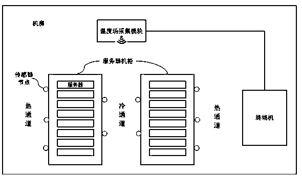
[0048] In an embodiment of the server room temperature field detection equipment system of the present invention, the schematic diagram of the equipment system is as follows image 3 shown. image 3 Among them, the temperature field detection equipment system in the server room includes:

[0049] engine room;

[0050] A server cabinet is arranged in the computer room, and a plurality of servers are integrated in the server cabinet;

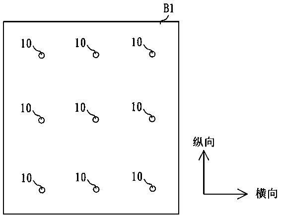
[0051] The temperature field map acquisition module includes a plurality of top-down sensor nodes respectively arranged on the cold side and the hot side of each server cabinet;

[0052] and a terminal, the terminal includes a calculation module and a storage device, the calculation module is used to substitute the temperature field map obtained by the temperature field acquisition module into the server room temperature field model database stored in the storage device, Calculate the reference actual operating temperature values ​​of all serve...

Embodiment 3

[0055] In the embodiment of the computer equipment used in the server room temperature field detection method and system of the present invention, the schematic diagram of the computer equipment is as follows Figure 6 shown. Figure 6 Among them, the computer device disclosed in the present invention includes a processor, a read interface, a communication interface, a memory, and a communication bus, wherein, the processor, the read interface, the communication interface and the memory are completed through the communication bus mutual communication. The memory is used to store the computer program of the present invention, and when the processor executes the computer program stored in the memory, the method steps of the present invention are realized.

[0056] In the computer-readable storage medium of the embodiment of the present invention, such as Figure 7 As shown, a computer program is stored thereon, and when the program is executed by a processor of a computer dev...


PUM


Abstract

The invention relates to a server room temperature field detection method and a system, and the method comprises the steps: a temperature field detection step: detecting and collecting the temperatures of the cold side and the hot side of each server cabinet in a machine room, and generating a temperature field diagram of the whole machine room according to the temperatures; a calculation step: introducing the temperature field diagram obtained in the temperature field detection step into a server room temperature field model database for calculation; and a judgment step of judging the runningstate of the server in each cabinet in the machine room according to the calculation result of the calculation step. According to the method, temperatures of a plurality of positions of hot sides andcold sides of all server cabinets in a machine room from top to bottom are collected; a temperature field diagram of the whole machine room is generated according to the temperatures, and the temperature field graph is introduced into a server machine room temperature field model database constructed in advance to obtain reference actual operation temperature values of all servers in the machineroom, so that the purpose of timely, accurately and intelligently monitoring the operation states of all the servers in the machine room is achieved.

Description

technical field [0001] The invention relates to the detection field, in particular to a detection method and system for the temperature field of a server room. Background technique [0002] A computer room is a space designed to provide continuous operation of a large number of computing servers. A building or site with a computer room is called a data center. For the servers in the computer room, due to the continuous calculation and data transmission of a large number of servers, the temperature in the computer room will rise sharply, thereby reducing the operating performance and energy consumption of the server. Therefore, the computer room must be equipped with air conditioning equipment to maintain the temperature at the optimum performance of the server. temperature. [0003] In view of the temperature monitoring requirements of the servers in the computer room, in the existing temperature control technology of the computer room, by arranging temperature sensors at s...

Claims


Application Information

Patent Timeline
Patent Type & Authority Applications(China)
IPC IPC(8): G06F11/30G05B17/02
CPCG05B17/02G06F11/3055G06F11/3058
Inventor 周健邱文渊陈勇崔世英沈博
Owner 广东优世联合控股集团股份有限公司
Learn More