optical lens
An optical lens and lens technology, applied in the field of optics, can solve problems such as rising costs, and achieve the effects of reasonable distribution, low cost, and reduced front port diameter
- Summary
- Abstract
- Description
- Claims
- Application Information
AI Technical Summary
Problems solved by technology
Method used
Image

Examples
Embodiment 1
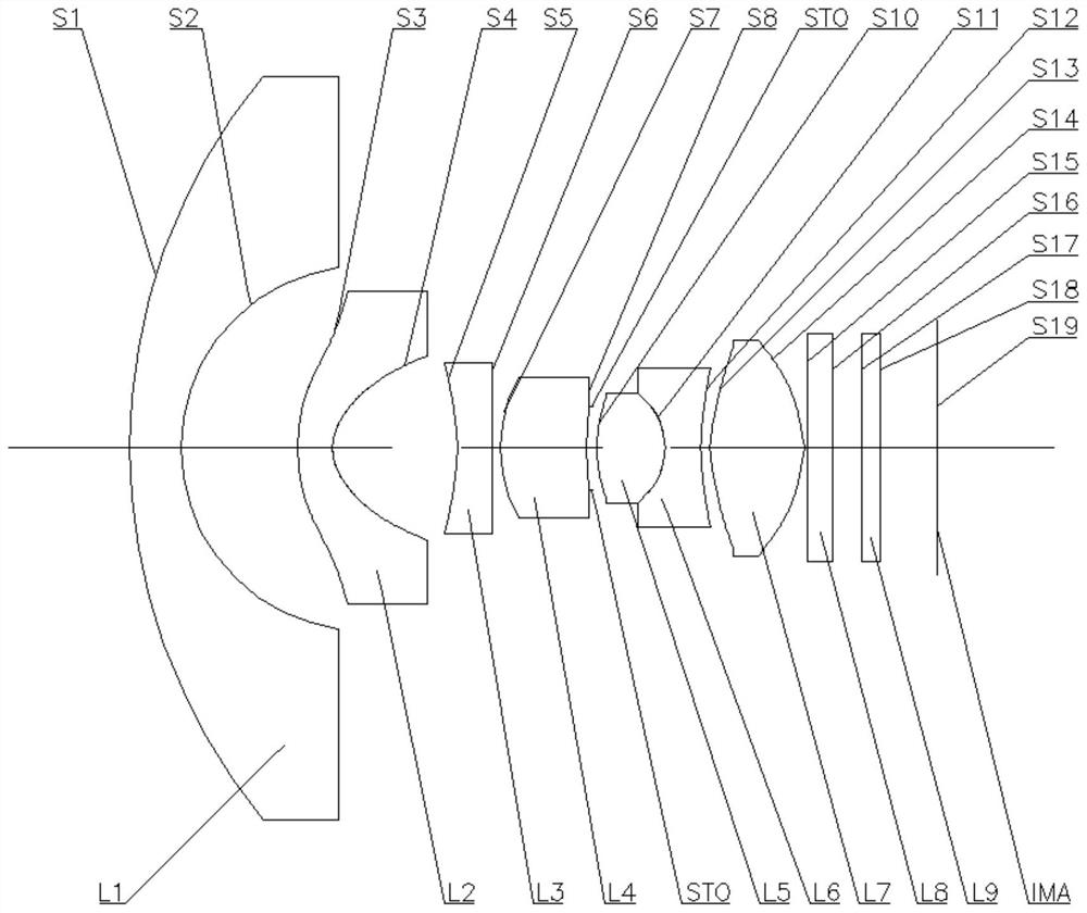
[0063] Refer to the following figure 1 An optical lens according to Embodiment 1 of the present application is described. figure 1 A schematic structural diagram of the optical lens according to Embodiment 1 of the present application is shown.
[0064] Such as figure 1 As shown, the optical lens sequentially includes a first lens L1, a second lens L2, a third lens L3, a fourth lens L4, a fifth lens L5, a sixth lens L6 and a seventh lens along the optical axis from the object side to the imaging side. Lens L7.
[0065] The first lens L1 is a meniscus lens with a negative refractive power and a convex surface facing the object side, the object side S1 is convex, and the image side S2 is concave. The second lens L2 is a meniscus lens with a negative refractive power and a convex surface facing the object side, the object side S3 is convex, and the image side S4 is concave. The third lens L3 is a meniscus lens with a negative refractive power and a convex surface facing the i...
Embodiment 2
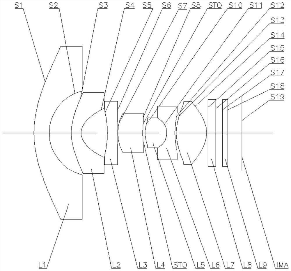
[0083] Refer to the following figure 2 An optical lens according to Embodiment 2 of the present application is described. figure 2 A schematic structural view of the optical lens according to Embodiment 2 of the present application is shown.
[0084] Such as figure 2 As shown, the optical lens sequentially includes a first lens L1, a second lens L2, a third lens L3, a fourth lens L4, a fifth lens L5, a sixth lens L6 and a seventh lens along the optical axis from the object side to the imaging side. Lens L7.
[0085] The first lens L1 is a meniscus lens with a negative refractive power and a convex surface facing the object side, the object side S1 is convex, and the image side S2 is concave. The second lens L2 is a meniscus lens with a negative refractive power and a convex surface facing the object side, the object side S3 is convex, and the image side S4 is concave. The third lens L3 is a meniscus lens with a negative refractive power and a convex surface facing the i...
Embodiment 3
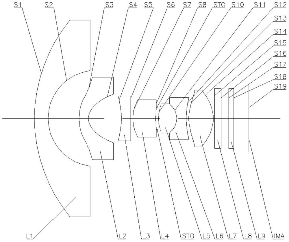
[0101] Refer to the following image 3 An optical lens according to Embodiment 3 of the present application will be described. image 3 A schematic structural diagram of an optical lens according to Embodiment 3 of the present application is shown.
[0102] Such as image 3 As shown, the optical lens sequentially includes a first lens L1, a second lens L2, a third lens L3, a fourth lens L4, a fifth lens L5, a sixth lens L6 and a seventh lens along the optical axis from the object side to the imaging side. Lens L7.
[0103] The first lens L1 is a meniscus lens with a negative refractive power and a convex surface facing the object side, the object side S1 is convex, and the image side S2 is concave. The second lens L2 is a meniscus lens with a negative refractive power and a convex surface facing the object side, the object side S3 is convex, and the image side S4 is concave. The third lens L3 is a meniscus lens with a negative refractive power and a convex surface facing t...
PUM
 Abstract
Description
Claims
Application Information
 - R&D
- Intellectual Property
- Life Sciences
- Materials
- Tech Scout
- Unparalleled Data Quality
- Higher Quality Content
- 60% Fewer Hallucinations
Browse by: Latest US Patents, China's latest patents, Technical Efficacy Thesaurus, Application Domain, Technology Topic, Popular Technical Reports.
© 2025 PatSnap. All rights reserved.Legal|Privacy policy|Modern Slavery Act Transparency Statement|Sitemap|About US| Contact US: help@patsnap.com