
Detecting mechanism of internal locking screw

A technology of detection mechanism and locking screw, which is applied in the direction of measuring device, adopting mechanical device, mechanical measuring device, etc., can solve the problems that affect the assembly accuracy of two boards and another board

Inactive Publication Date: 2019-11-05
DONGGUAN XIANGFEI INTELLIGENT EQUIP TECH CO LTD
View PDF0 Cites 0 Cited by
  • Summary
  • Abstract
  • Description
  • Claims
  • Application Information

AI Technical Summary

Problems solved by technology

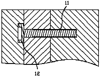
[0002] Screw is a common fastener with a wide range of applications, such as figure 2 As shown, it is a kind of screw rod 4 for internal locking. Firstly, its rod part 11 needs two plates to be locked. After the board is locked, install the locked whole with another board, and the head at this time plays a role in limiting the installation of the other board. This screw is defined as the screw used for internal locking. , for this type of screw, one of the important data is whether the center of the head and the rod are on the same straight line. If there is an offset, it will inevitably affect the assembly accuracy of the two locked plates and the other plate, so it is necessary to It performs eccentricity detection, and most of the existing eccentricity detections are manually using some equipment to conduct a single spot check on the screw, so there will be the existence of individual eccentric screws

Method used


Image

  • Detecting mechanism of internal locking screw
  • Detecting mechanism of internal locking screw
  • Detecting mechanism of internal locking screw

Examples


Embodiment Construction

[0019] In order to enable those skilled in the art to better understand the technical solution of the present invention, the present invention will be described in detail below in conjunction with the accompanying drawings. The description in this part is only exemplary and explanatory, and should not have any limiting effect on the protection scope of the present invention. .

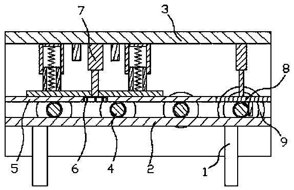
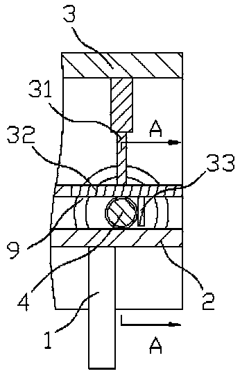
[0020] Such as figure 1 As shown, the specific structure of the present invention is: a detection mechanism for an internal locking screw, including a delivery trough 2 that is arranged on the bracket 1 and can adjust the inclination, and the upper side plate of the delivery trough 2 is provided with an upper Frame 3, and the rear portion of the delivery trough 2 is provided with a head matching groove that cooperates with the head 12 of the screw rod 4, and the front side plate of the delivery trough 2 is also provided with the bottom surface of the delivery trough 2 to form a rod 11 delivery frame ...


PUM


Abstract

The invention relates to a detecting mechanism of an internal locking screw. The detecting mechanism comprises a conveying tank arranged on a support. The inclination degree of the conveying tank canbe adjusted. An upper frame is arranged at the upper portions of side plates of the conveying tank. A head portion matched groove matched with a head portion of the screw is formed in the rear portionof the conveying tank. A pressing block for forming a rod portion conveying frame together with the bottom face of the conveying tank is arranged on the front side plate of the conveying tank. A detection clamping device matched with the screw coming out of the tail end of the pressing block is arranged on the lower side of the upper frame. An eccentric detecting device matched with the screw clamped by the detection clamping device is arranged outside the rear side plate of the conveying tank. By means of the detecting mechanism of the internal locking screw, conveying is conducted through the inclined conveying tank; in cooperation with the detection clamping device, the screw can be clamped, and therefore it can be ensured that the position of the rod portion of the screw at the detecting station is determined; in cooperation with the eccentric detecting device, the continuous eccentric detecting of the screw can be realized.

Description

technical field [0001] The invention relates to the field of detection equipment, in particular to a detection mechanism for an internal locking screw. Background technique [0002] Screw is a common fastener with a wide range of applications, such as figure 2 As shown, it is a kind of screw rod 4 for internal locking. Firstly, its rod part 11 needs two plates to be locked. After the board is locked, install the locked whole with another board, and the head at this time plays a role in limiting the installation of the other board. This screw is defined as the screw used for internal locking. , for this type of screw, one of the important data is whether the center of the head and the rod are on the same straight line. If there is an offset, it will inevitably affect the assembly accuracy of the two locked plates and the other plate, so it is necessary to It performs eccentricity detection, and most of the existing eccentricity detections are to manually use some equipment ...

Claims


Application Information

Patent Timeline
IPC IPC(8): G01B21/24G01B5/02G01B7/02
CPCG01B5/02G01B7/02G01B21/24
Inventor 黄军梅李德源
Owner DONGGUAN XIANGFEI INTELLIGENT EQUIP TECH CO LTD
Learn More