Solar cavity receiver

A solar energy and receiver technology, which is applied to solar collectors, components of solar collectors, solar thermal energy, etc., can solve the difficulty of sealing glass tubes and metal tubes, the difficulty of maintaining internal vacuum, and the decline of light-to-heat conversion efficiency. and other problems, to achieve the effect of reuse, reduce heat loss, and improve photothermal efficiency

Pending Publication Date: 2019-11-05
NO 719 RES INST CHINA SHIPBUILDING IND
View PDF0 Cites 0 Cited by
  • Summary
  • Abstract
  • Description
  • Claims
  • Application Information

AI Technical Summary

Problems solved by technology

At present, the solar receiver commonly used in the trough-type photothermal utilization system is a straight-through high-temperature vacuum tube. Although its heat collection performance is good, its cost is relatively high, and the internal vacuum is not easy to maintain. It is difficult to seal the glass tube and the metal tube. Leaking its light-to-heat conversion efficiency will drop significantly

Method used


Image

  • Solar cavity receiver
  • Solar cavity receiver
  • Solar cavity receiver

Examples


Embodiment Construction

[0027] The following will clearly and completely describe the technical solutions in the embodiments of the present invention in conjunction with the embodiments of the present invention. Obviously, the described embodiments are only part of the embodiments of the present invention, not all of them. Based on the implementation manners in the present invention, all other implementation manners obtained by persons of ordinary skill in the art without making creative efforts belong to the scope of protection of the present invention.

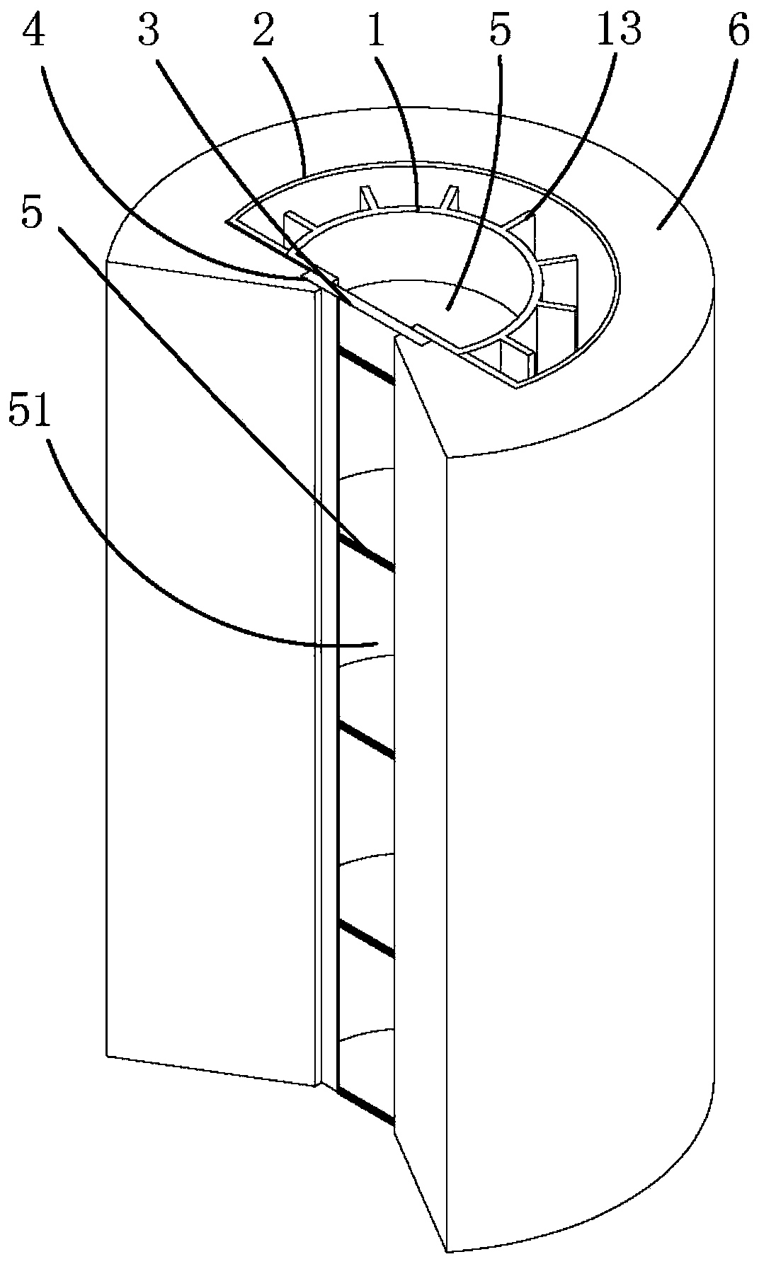
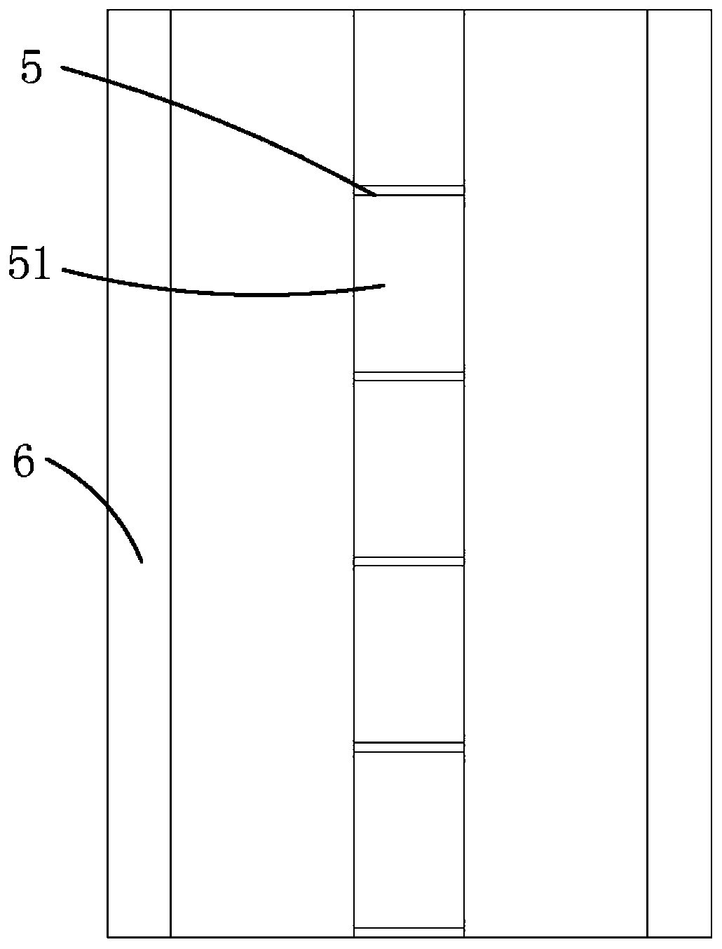
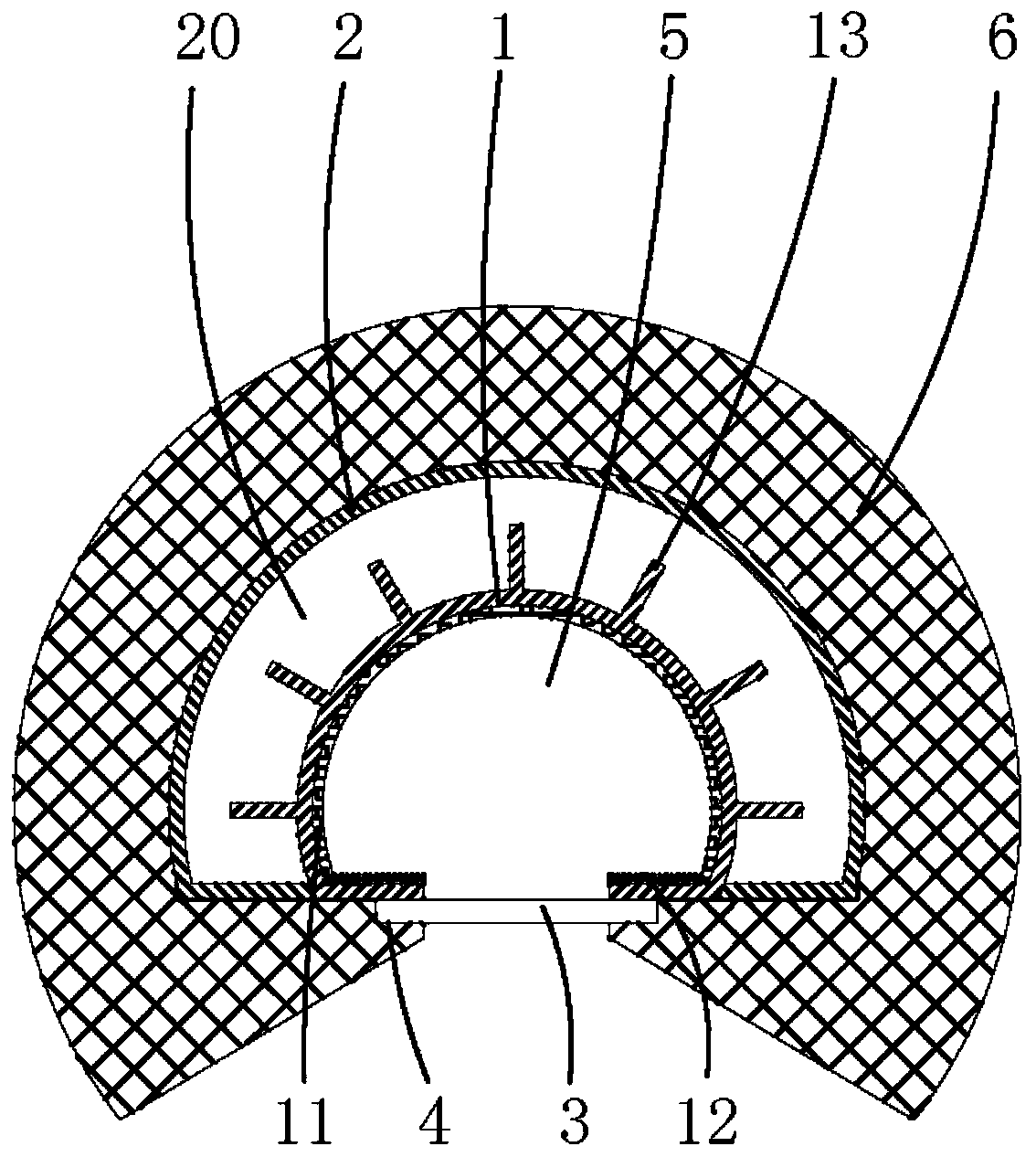
[0028] Such as figure 1 to combine figure 2 and image 3 As shown, the present invention provides a solar cavity receiver, which includes a first cylinder 1 , a second cylinder 2 , a lens 3 , several partitions 5 , and an insulation layer 6 . The outside of the first cylinder 1 is provided with a second cylinder 2, the surface of the second cylinder 2 is fixedly connected with the surface of the first cylinder 1, and a hollow inner cavity 20 is ...


PUM


Abstract

The invention provides a solar cavity receiver. The solar cavity receiver comprises a first cylinder, a second cylinder and a lens; the second cylinder is arranged on the outer side of the first cylinder; the surface of the second cylinder is fixedly connected with the surface of the first cylinder; a hollow inner cavity is formed between the first cylinder and the second cylinder; the first cylinder is provided with a window for enabling light rays to emit in; the lens is embedded in the window; the first cylinder is provided with multiple separation plates; the separation plates are fixedlyconnected with the inner surface of the first cylinder; and the separation plates are arranged at intervals for dividing the internal of the first cylinder into multiple disconnected compartments. Thehollow inner cavity is formed between the first cylinder and the second cylinder; sunlight enters the first cylinder by the window for heating the first cylinder; the first cylinder exchanges heat ofa heat transfer medium in the inner cavity to realize photothermal conversion; through the separation plates arranged at intervals, the air flowing in the first cylinder can be reduced, so that the convection heat exchange loss is reduced; and the compartments between the separation plates can be further closed through the lens in the window.

Description

technical field [0001] The invention relates to a cavity heat absorber, in particular to a solar cavity receiver. Background technique [0002] Most areas in my country are located between 18°-45° north latitude, and nearly two-thirds of the area has an average annual sunshine time of more than 2000h, which is rich in solar energy resources and can be used for heat collection. Existing solar collectors are mainly divided into two categories: non-focused solar collectors and focused solar collectors. The non-focused collector does not need to track the sun, the temperature of the heat transfer medium is generally below 100°C, and the energy quality is not high, but its cost is low, and it can be used in solar heating, domestic water heating, etc., and belongs to the medium and low temperature solar collector. Concentrated solar collectors are divided into two types: point focus and line focus, which can concentrate solar energy on a certain area to a smaller area, thus obtai...

Claims


Application Information

Patent Timeline
Patent Type & Authority Applications(China)
IPC IPC(8): F24S23/30F24S70/20F24S23/70F24S80/00
CPCF24S23/30F24S70/20F24S23/70F24S80/00Y02E10/40
Inventor 段晨王祖华国占东柳超张思平叶梦熊常华伟
Owner NO 719 RES INST CHINA SHIPBUILDING IND
Why Eureka
Try Eureka