
Method for automatically identifying cavitation state of pump

An automatic identification and cavitation technology, applied in pump control, non-variable-capacity pumps, machines/engines, etc., can solve the problems of low efficiency, low sensitivity and low efficiency of manual analysis, and achieve automatic identification and diagnosis, reduce effect of loss

Active Publication Date: 2019-11-05
西安因联信息科技有限公司
View PDF3 Cites 8 Cited by
  • Summary
  • Abstract
  • Description
  • Claims
  • Application Information

AI Technical Summary

Problems solved by technology

These methods have a certain monitoring and diagnosis effect, but the first method requires a certain amount of experience and knowledge, and the efficiency is low; the sensitivity of the latter method is relatively low; compared with the former two methods, the vibration signal has a better monitoring effect on cavitation faults. Better, but manual analysis is still not efficient

Method used


Image

  • Method for automatically identifying cavitation state of pump
  • Method for automatically identifying cavitation state of pump
  • Method for automatically identifying cavitation state of pump

Examples


Embodiment Construction

[0051] The present invention is further described below in conjunction with accompanying drawing:

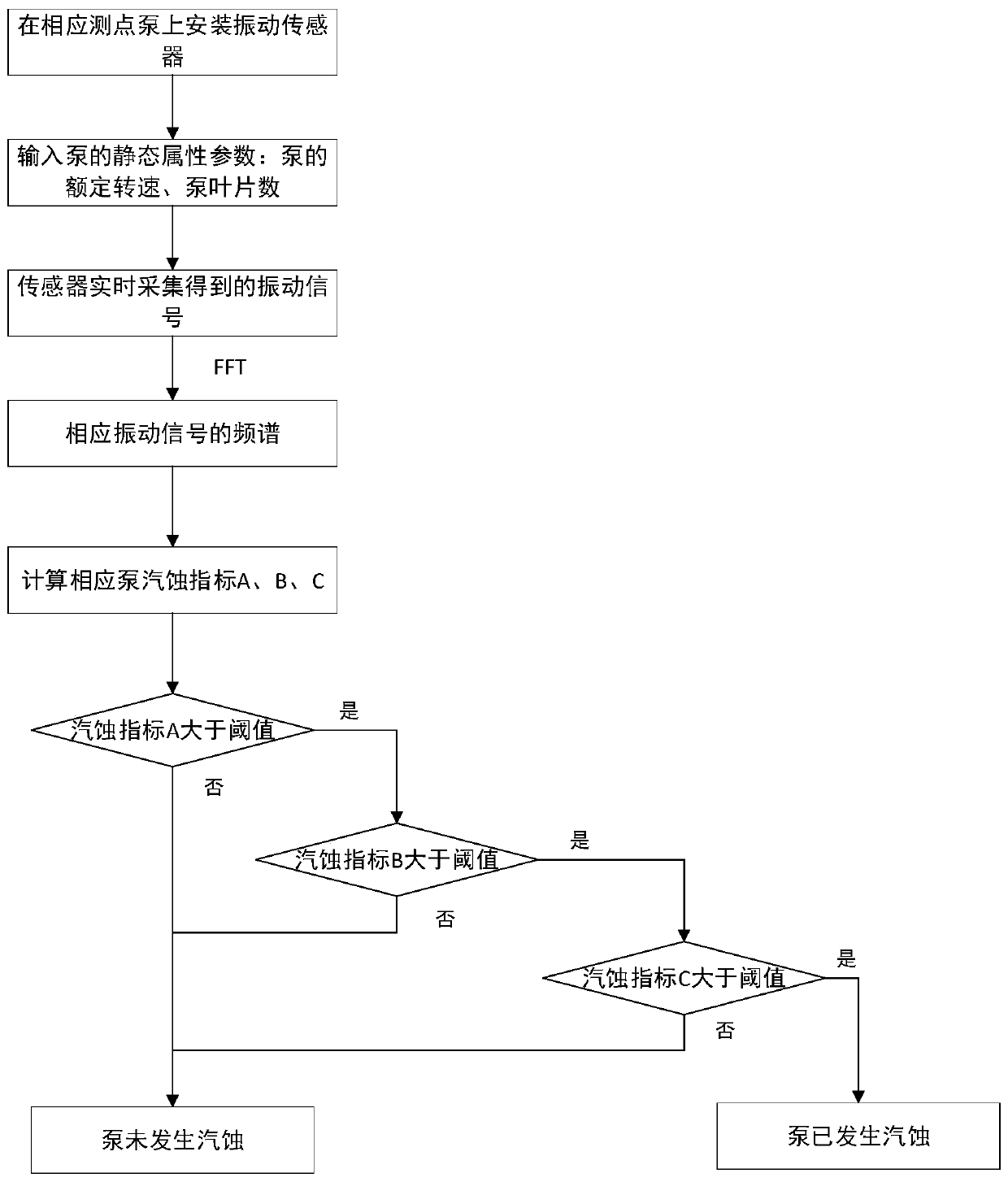
[0052] see Figure 1 to Figure 8 , a pump cavitation state automatic identification method, comprising the following steps:

[0053] Step 1, collect the pump vibration measuring point signal through the sensor, and collect the static parameters of the pump at the same time;

[0054] Step 2, through the speed signal and static parameters collected in step 1, perform FFT fast Fourier transform on the signal to obtain the frequency spectrum of the signal, and calculate the blade passing frequency of the pump;

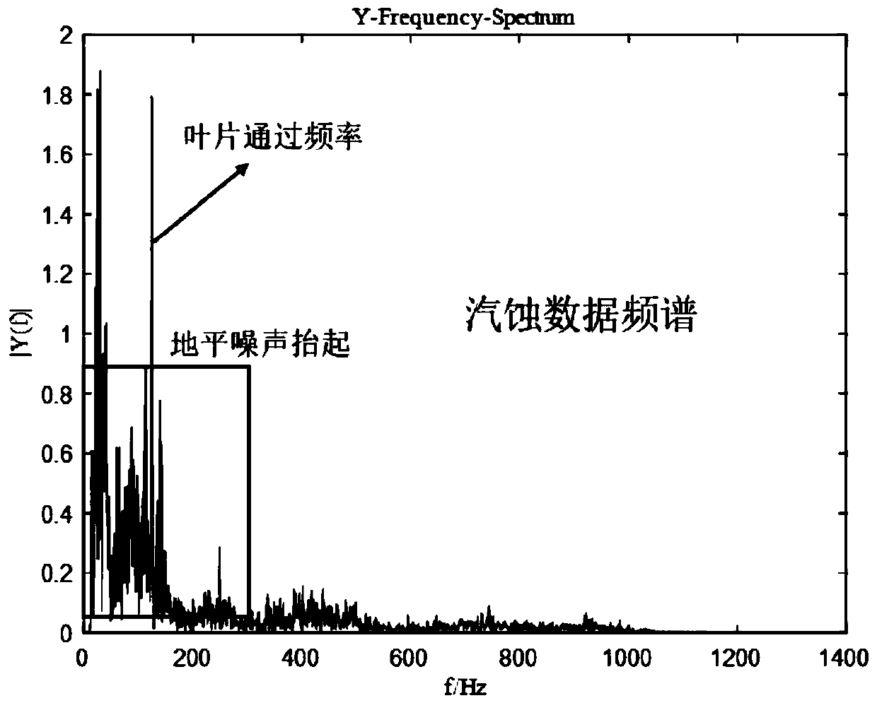
[0055] Step 3, extract the corresponding cavitation index according to the mechanism of pump cavitation and the lifting vibration characteristics of horizon noise caused by high blade passing frequency accompanied by high random vibration;

[0056] Step 4, by judging the ratio of 1 to 2 times the passing frequency of blades and the threshold value of the cavitation index, ...


PUM


Abstract

The invention relates to a method for automatically identifying the cavitation state of a pump. The method comprises the following steps: 1, acquiring a pump vibration measuring point signal and collecting static parameters of the pump at the same time; 2, calculating the blade passing frequency of the pump; 3, extracting a corresponding cavitation index; and 4, automatically identifying the cavitation state. By the method for automatically identifying the cavitation state of the pump based on vibration spectrum analysis, rapid identification and diagnosis are realized when pump cavitation occurs. According to the method based on combination of cavitation failure mechanism and vibration spectrum, automatic identification and diagnosis of pump cavitation are realized. Compared with the traditional ear hearing and artificial diagnosis analysis methods, the method has the advantages that the monitoring and diagnosis efficiency of pump cavitation failure is improved to a great degree whilemanual participation is reduced. Thereby, cavitation failure is discovered timely and loss caused by pump cavitation is reduced.

Description

technical field [0001] The invention belongs to the field of state monitoring of mechanical equipment, and in particular relates to an automatic recognition method of pump cavitation state. Background technique [0002] Pump cavitation is due to the fact that the partial pressure of the liquid flowing in the pump is lower than the vaporization pressure of the liquid at a certain temperature, the impurities in the liquid, the tiny solid particles, and the gas nuclei in the gap between the liquid and the solid interface , will quickly grow into visible bubbles, and these bubbles will burst when they flow into the high-pressure area, causing certain damage to the metal surface of the flow channel. [0003] As a general-purpose machine widely used in the industrial field, the normal operation of the pump is of great significance to the safe and efficient production of enterprises. Frequent cavitation failures will cause the pump to produce abnormal vibration and noise, and will...

Claims


Application Information

Patent Timeline
IPC IPC(8): F04D15/00
CPCF04D15/00F04D15/0088
Inventor 彭朋田秦胡翔吕芳洲夏立印
Owner 西安因联信息科技有限公司
Learn More