Method and system for variable displacement engine diagnostics

An engine and actuation technology, applied in the direction of engine components, combustion engine, engine control, etc., can solve the problem that the fuel injection timing cannot be set correctly

Pending Publication Date: 2019-11-05
FORD GLOBAL TECH LLC
View PDF1 Cites 0 Cited by
  • Summary
  • Abstract
  • Description
  • Claims
  • Application Information

AI Technical Summary

Problems solved by technology

In either case, fuel injection timing may not be set correctly without crankshaft information

Method used


Image

  • Method and system for variable displacement engine diagnostics
  • Method and system for variable displacement engine diagnostics
  • Method and system for variable displacement engine diagnostics

Examples


Embodiment Construction

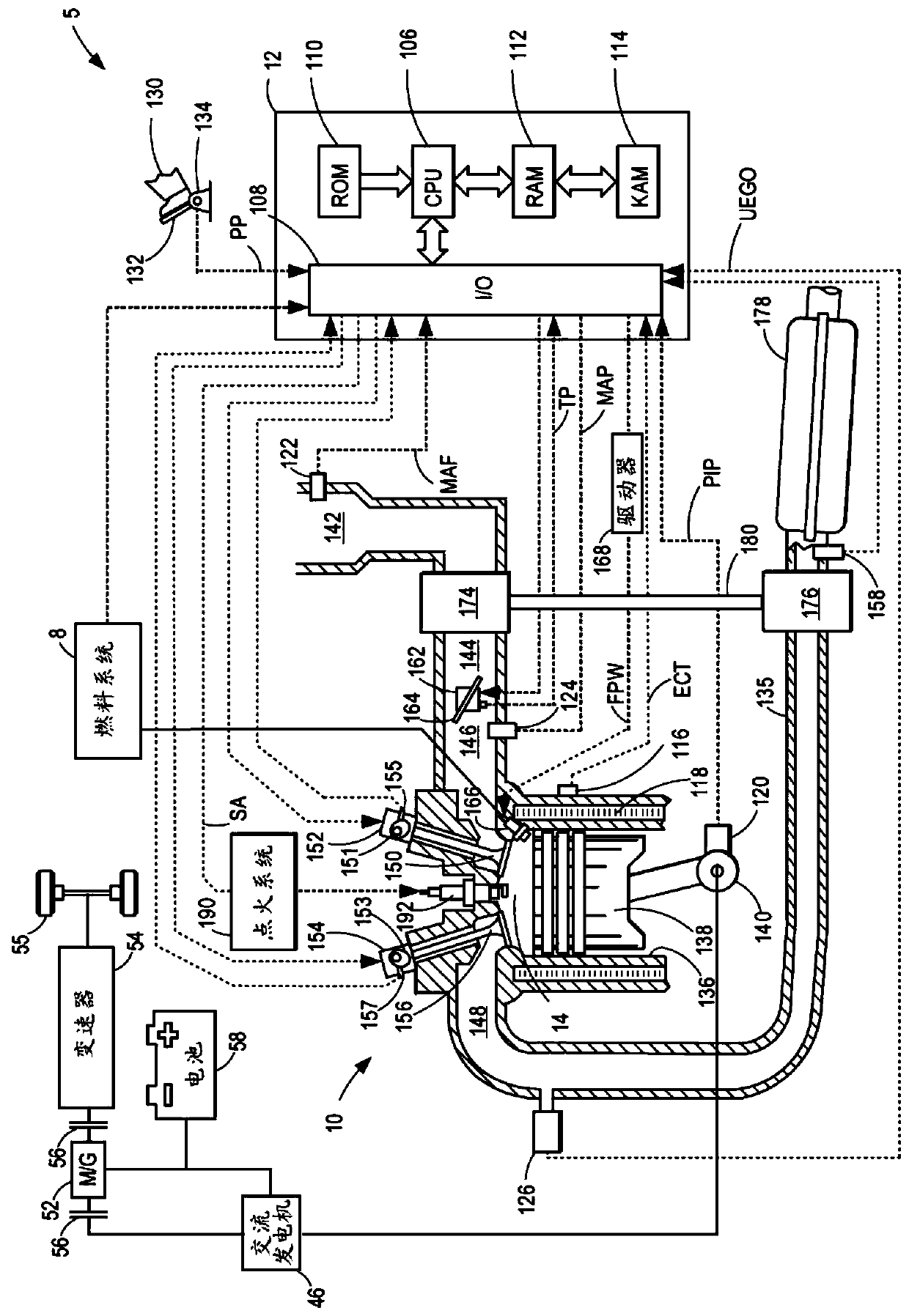
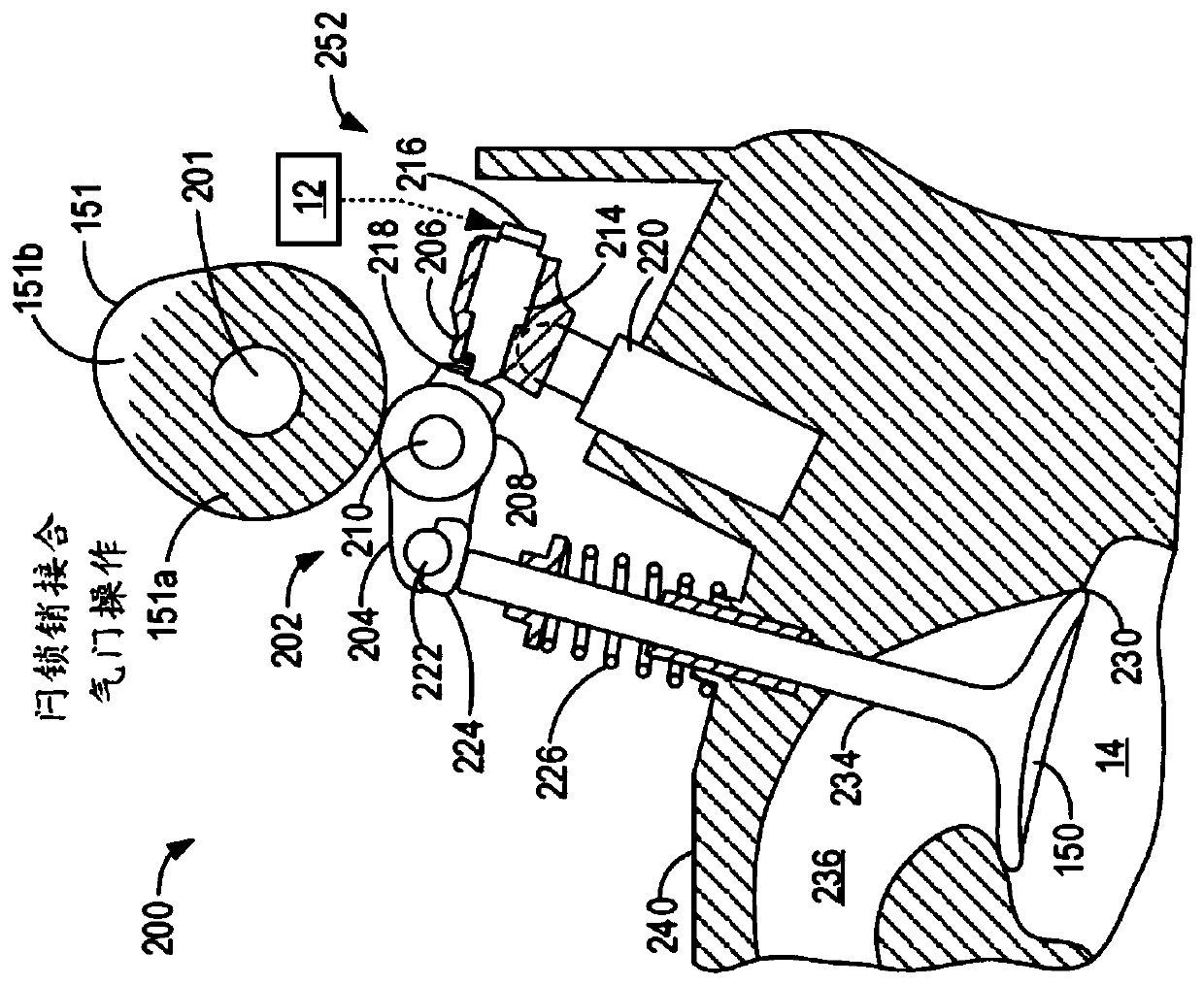
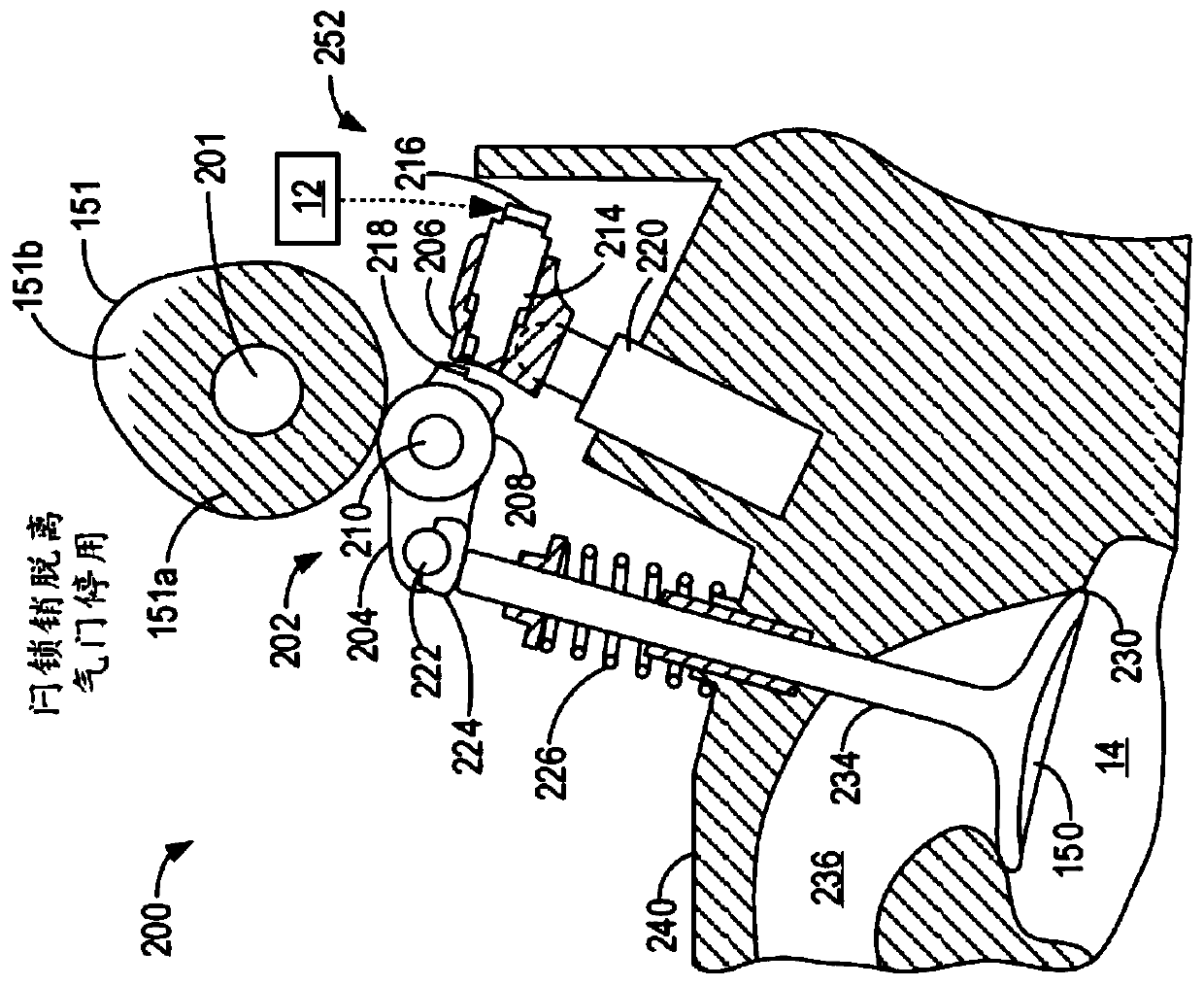
[0024] The following description relates to controls for engines (eg, figure 1 A system and method for a cylinder valve deactivation mechanism of an engine system). The cylinder valve deactivation mechanism may include an electrically latched rocker arm mechanism, such as in 2A to 2D Electric latch rocker mechanism depicted in . For example, by actuating a latch pin of the valve deactivation mechanism between an engaged position and a disengaged position via energizing an associated solenoid, the corresponding cylinder valve may be placed between an active state and a deactivated state switch, as in image 3 summarized in the table. For example, according to Figure 4 method and about Figure 11 To illustrate, the latch pin position, and thus the valve state, may be changed during engine start-up or shut-down, and, for example, according to Figure 5 method, the latch pin position and thus the valve state may be changed during transitions to and from a variable displace...


PUM


Abstract

The present invention provides a method and a system for variable displacement engine diagnostics. The methods and systems are provided for diagnosing a cylinder valve deactivation mechanism in an engine system having cam-actuated valves. Movement of a latch pin of the deactivation mechanism is inferred from an induction current generated by a solenoid coupled to the latch pin, and the inferred movement is used to diagnose operation of cylinder valve deactivation mechanism. The inferred movement and a profile of the induction current is also used to estimate camshaft and crankshaft timing forimproved cylinder fuel delivery in the absence of a camshaft sensor.

Description

technical field [0001] The present application relates to a method and system for monitoring actuation of a cylinder valve deactivation mechanism in a variable displacement engine (VDE). Background technique [0002] The engine may include a cam-based system for controlling intake and exhaust valve timing. Wherein the cam is coupled to the camshaft. Because valves control the flow of air and fuel into engine cylinders for combustion, camshaft positions may be required so that accurate fueling and spark timing can be provided for reliable combustion and low emissions. For example, accurate and timely knowledge of camshaft position during engine starts may enable coordination of spark timing and fuel delivery in the engine and achieve more repeatable engine starts. [0003] Typically, an engine controller retrieves camshaft position information using a position sensor coupled to the camshaft. However, such sensors are expensive. Additionally, sensors may be prone to degrad...

Claims


Application Information

Patent Timeline
Patent Type & Authority Applications(China)
IPC IPC(8): F02B77/08F02D13/06F02D41/38F01L13/00
CPCF01L13/0005F01L2013/001F02B77/08F02D13/06F02D41/38F01L2001/186F01L2013/101F01L2305/00F01L2800/01F01L2800/03F01L2800/11F01L2800/14F01L2820/041F02D41/0087F02D41/042F02D41/221F02D2041/0012F02D2250/21Y02T10/12Y02T10/40F01L1/18F01L13/0036F01L2800/18F02D13/0207
Inventor 格雷戈里·麦康维尔约瑟夫·乌雷埃米·卡尔尼克
Owner FORD GLOBAL TECH LLC
Why Eureka
Try Eureka