


Quick Research
Generate reliable direction feasibility study reports for your R&D in just a few steps.

Technical Q&A
Discover and master advanced knowledge NOW. Basics, ideas, possibilities, all at once.

Find Solutions
As an expert in R&D theories, this can generate solutions to your technical problems instantly.

Evaluate Feasibility
Analyze your overall solution with one click, know your potential R&D risks in advance.

Monitor Landscape
Get weekly tech updates, stay abreast of the latest tech innovations and key insights.
Drilling boom and rock drilling rig
A drilling and cantilever technology, which is applied in drilling equipment, drilling equipment and methods, and earth-moving drilling and mining, etc., to achieve the effects of improving stretchability, good stretchability, and durable weight.
- Summary
- Abstract
- Description
- Claims
- Application Information
AI Technical Summary
Problems solved by technology
Method used
Image

Examples
Embodiment Construction
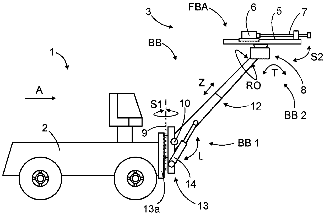
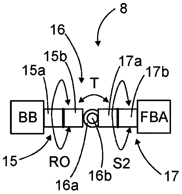
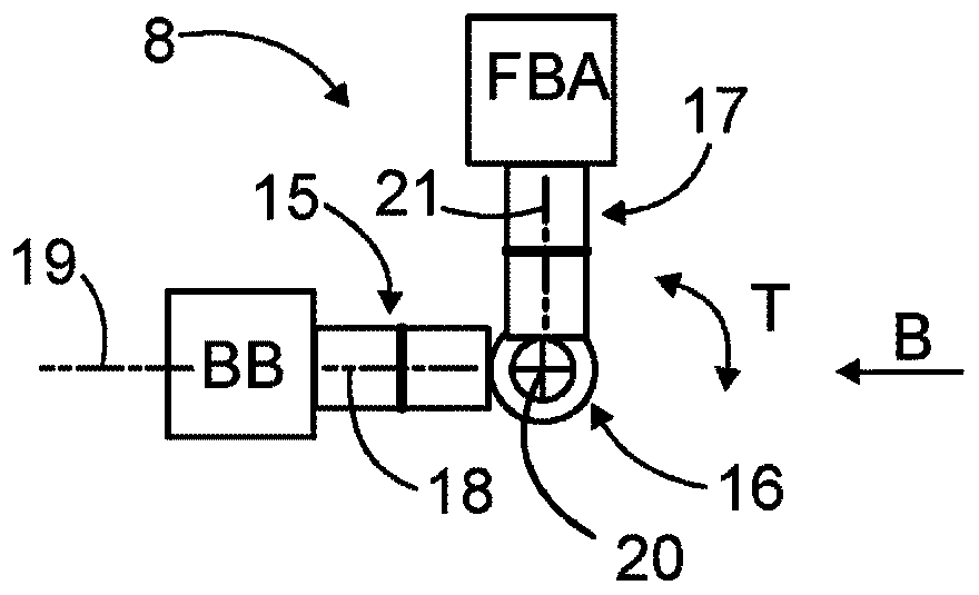
[0037] figure 1A rock drilling rig 1 for face drilling during tunneling is shown. The rock drilling rig 1 comprises a movable transport carrier 2 and one or more drilling booms 3 connected to the transport carrier 2 . When the drilling rig comprises a plurality of drilling booms, the drilling rig is often referred to as a drilling jumbo. The drilling boom 3 comprises a base boom part BB which is an elongated structure and whose first end BB1 is movably connected to a transport carrier. At the distal second end BB2 of the base cantilever portion is the feed beam assembly FBA. The feed beam assembly FBA may comprise a feed beam 5 and a rock drilling machine 6 supported on the feed beam 5 . The rock drilling machine 6 may comprise a shank at the front end of the rock drilling machine 6 for connecting the tool 7 . The feed beam assembly FBA is connected to the second end BB2 of the base boom section by means of a front joint arrangement 8 (may also be referred to as a wrist jo...
PUM
 Abstract
Description
Claims
Application Information
 - R&D Engineer
- R&D Manager
- IP Professional
- Industry Leading Data Capabilities
- Powerful AI technology
- Patent DNA Extraction
Browse by: Latest US Patents, China's latest patents, Technical Efficacy Thesaurus, Application Domain, Technology Topic, Popular Technical Reports.
© 2024 PatSnap. All rights reserved.Legal|Privacy policy|Modern Slavery Act Transparency Statement|Sitemap|About US| Contact US: help@patsnap.com