
Three-bar oscillating mechanical arm for feeding and discharging glass

A three-link, swinging technology, applied in the directions of manipulators, program-controlled manipulators, chucks, etc., can solve the problems of adjusting the swing arm of glass loading and unloading, low glass loading and unloading efficiency, and low accuracy of placement position, etc., to achieve stable operation. High, improve the conveying efficiency, the effect of strong versatility

Pending Publication Date: 2019-11-05
佛山市顺德区晶睿机电科技有限公司
View PDF0 Cites 2 Cited by
  • Summary
  • Abstract
  • Description
  • Claims
  • Application Information

AI Technical Summary

Problems solved by technology

[0006] 1) The continuity of loading and unloading is low. The existing loading and unloading mechanism can only wait for the previous glass to be transferred and transported to the platform before the swing arm of glass loading and unloading can drive the glass adsorption device to swing away from the conveying platform. The waiting period is long , the glass loading and unloading efficiency is low;
[0007] 2) It is difficult to adjust the swing angle of the upper and lower glass swing arms according to the number of glasses stacked on the glass shelf. Only the installation position of the glass shelf can be adjusted to meet the needs of glass placement. The accuracy of the placement position is low and the versatility is low Difference

Method used


Image

  • Three-bar oscillating mechanical arm for feeding and discharging glass
  • Three-bar oscillating mechanical arm for feeding and discharging glass
  • Three-bar oscillating mechanical arm for feeding and discharging glass

Examples


Embodiment Construction

[0032] The present invention will be further described below in conjunction with the accompanying drawings.

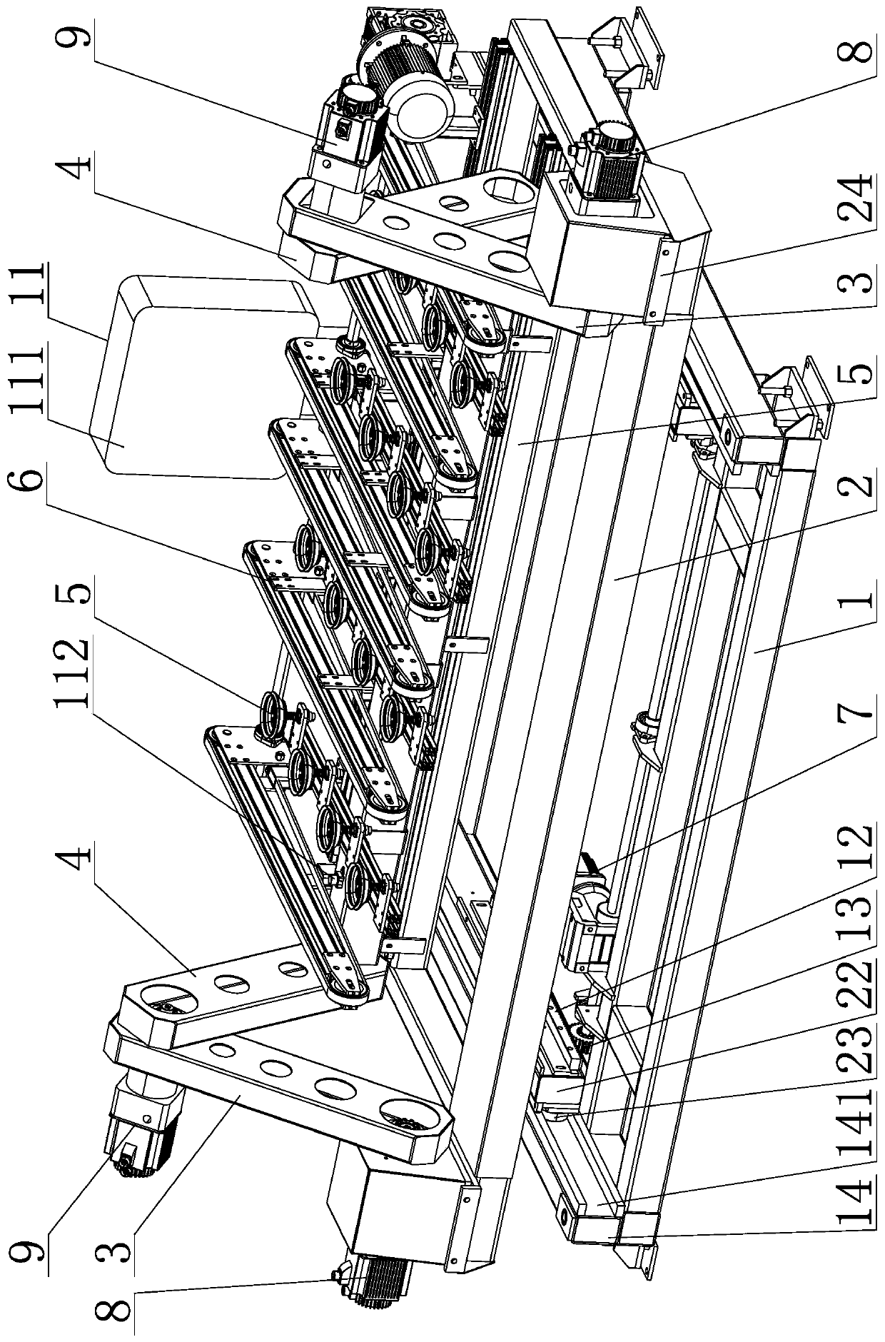
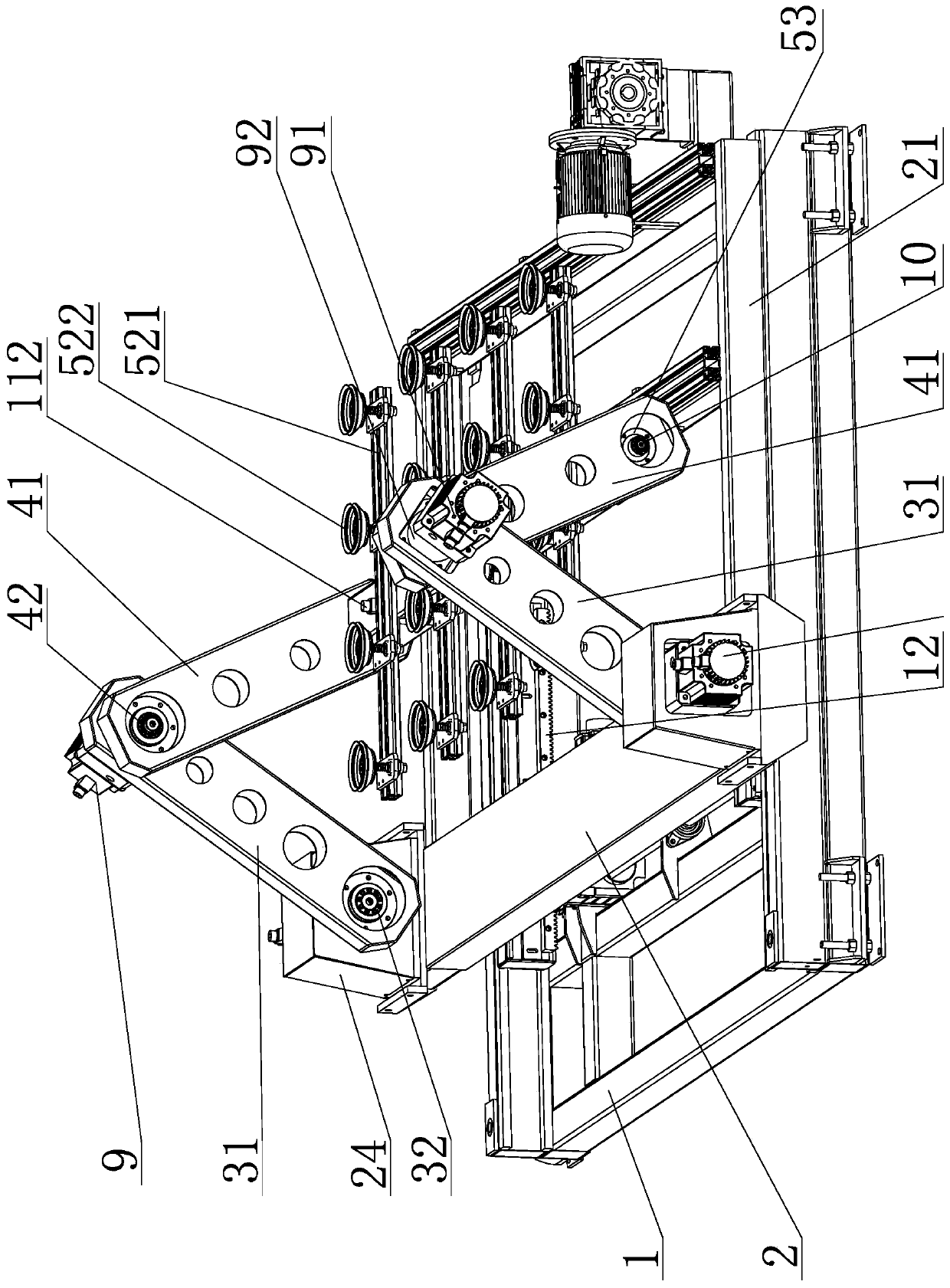
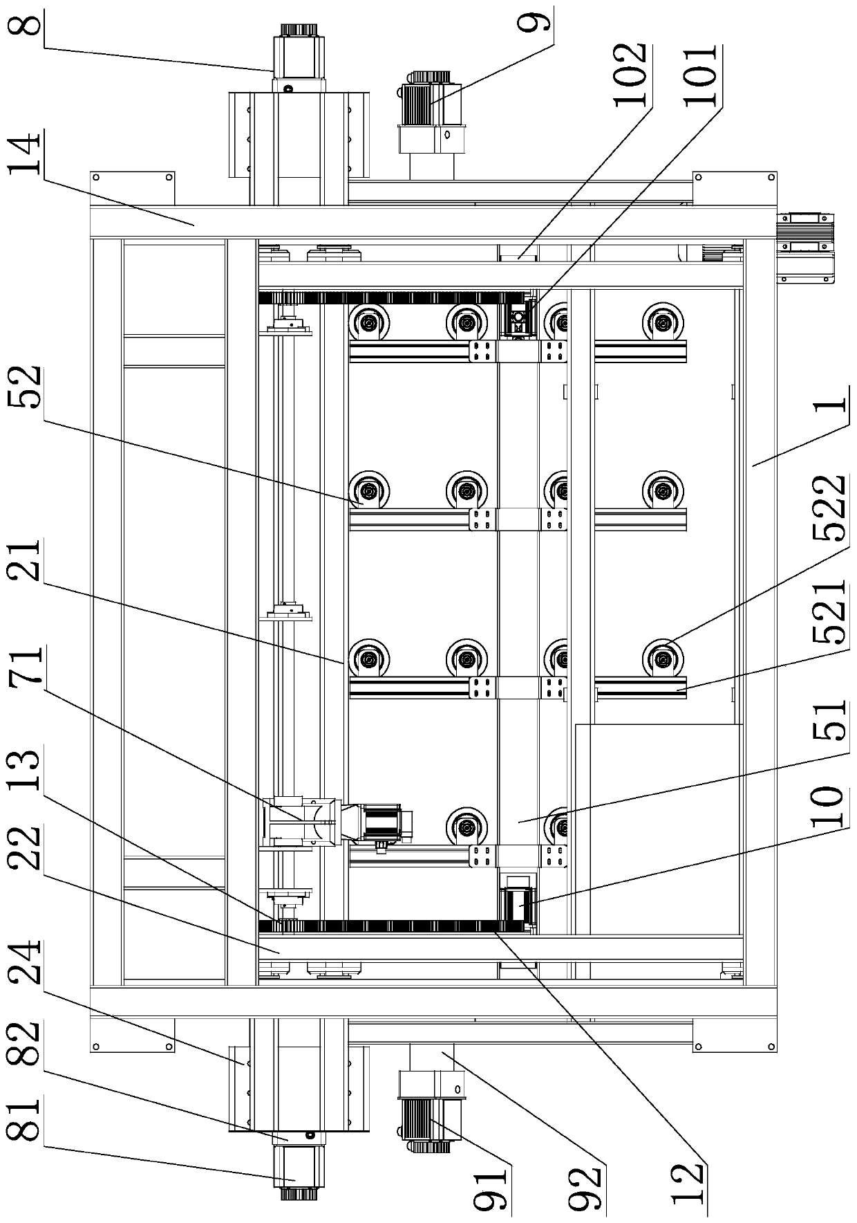
[0033] According to attached Figure 1 to Figure 4 As shown, the three-link swinging mechanical arm for loading and unloading glass of the present invention includes a fixed chassis 1, a movable assembly frame 2, a primary swing assembly 3, a secondary swing assembly 4, a rotary suction cup assembly 5, a glass Delivery platform 6. The glass conveying platform 6 is installed on the movable assembly frame 2 , and the movable assembly frame 2 is slidably connected to the fixed chassis 1 . The positioning end shaft of the first-level swing combination 3 is connected to the movable combination frame 2, the swing end shaft of the first-level swing combination 3 is connected to the positioning end of the second-level swing combination 4, and the swing end of the second-level swing combination 4 is connected to the rotary Suction cup combination 5-axis connection.

[0034] ...


PUM


Abstract

The invention provides a three-bar oscillating mechanical arm for feeding and discharging glass. The three-bar oscillating mechanical arm comprises a fixed underframe, a movable combined frame, primary swing combinations, secondary swing combinations, rotary sucker combinations and glass transporting platforms, wherein the movable combined frame is connected onto the fixed underframe in a slidingmanner; the primary swing combinations, the secondary swing combinations and the rotary sucker combinations are connected in sequence through shafts; a movable driving component is mounted on the fixed underframe, primary driving components and secondary driving components are mounted on the movable combination frame, and rotary driving components are mounted on the rotary sucker combinations; a control combiner is arranged on the fixed underframe, and controls the glass transporting platforms, the movable driving component, the primary driving components, the secondary driving components andthe rotary driving components to act in sequence; glass feeding and discharging are realized accurately by adopting a multi-stage link type swing way, so that the waiting period is shortened, and thetransporting efficiency is improved, meanwhile, glass is accurately fed and discharged under the condition that the swing angle is not changed, the generality is high, and the glass production qualityis ensured.

Description

technical field [0001] The invention relates to the technical field of hollow glass production, in particular to a three-link swinging mechanical arm for loading and unloading glass. Background technique [0002] At present, insulating glass is a high-efficiency insulation glass made of two or more pieces of glass, using a high-strength air-tight composite adhesive to bond the glass pieces to an aluminum alloy frame containing a desiccant. Because the performance of insulating glass is superior to that of ordinary double-layer glass, it is widely used in residences, restaurants, hotels, office buildings, schools, hospitals, shops and other occasions that require indoor air conditioning, and can also be used in trains, automobiles, ships, and freezers. Doors and windows etc. [0003] However, on the insulating glass production line, it is necessary to move the paired two or three pieces of glass to the production line. In this process, manual handling is required, especiall...

Claims


Application Information

Patent Timeline
IPC IPC(8): B25J9/04B25J9/10B25J9/12B25J15/06
CPCB25J9/04B25J9/126B25J9/102B25J15/0616
Inventor 曹浪
Owner 佛山市顺德区晶睿机电科技有限公司
Learn More