Roller body manufacturing device and technology

A system and roller body technology, applied in the field of composite pipe preparation, can solve the problems of waste of raw materials, inability to transport by itself, damage to the surface of the roller body, etc., and achieve the effect of reducing work intensity, facilitating assembly line operation, and eliminating manpower

Pending Publication Date: 2019-11-05
SHANDONG GUANGTAI ENVIRONMENTAL TECH CO LTD
View PDF0 Cites 0 Cited by
  • Summary
  • Abstract
  • Description
  • Claims
  • Application Information

AI Technical Summary

Problems solved by technology

[0003] Since the roller body can be applied to many downstream equipment, such as ironing machine, cloth spreading machine, cloth feeding machine, folding machine, stacker and other linen finishing equipment, the roller body is required, and each equipment needs There are several types of roll bodies, so the order of roll bodies appears to be small and multi-specification. At present, there is no certain standard for the type of roll bodies in China. Generally, they are enterprise standards, and many companies have led to many standards. Rollers of the same length Body may have different requirements for roundness and beating;
[0004] In the existing process, the entire roller body preparation process mostly adopts the traditional single-person processing method, that is, one person completes the shaft assembly, welding and sends it to the polishing place for polishing. The shaft and welding requirements are generally very high, and skilled workers must be required to operate. The labor cost of workers is getting higher and higher, and skilled workers are becoming scarcer, resulting in low processing efficiency; there are also some manufacturers that install shafts and welding separately, but the roller body The quality of the rollers is relatively heavy. After the processing is completed, it cannot be transported by itself. Only the next process needs to be piled up on the spot. Later, it will be moved with the help of a transport trolley or a crane. Batch processing requirements are generally different, and it is easy to misplace the processing standards of each batch, wasting raw materials, and the cost of each roll body is about 2,000 yuan. At the same time, the company has to pay workers' wages, resulting in a serious loss of product profits. thus losing competitiveness;
[0005] In addition, the transport volume of the roller body is large through the transport trolley or crane. On the one hand, multiple roller bodies are easy to collide with each other and damage the surface of the roller body. On the other hand, it is difficult to directly transport the roller body to the worker's station, resulting in Workers need to transport the roller body to their own work station. Although the distance is very close and generally no more than 2m, the quality of the roller body is relatively large. If 20 roller bodies are processed every day, the roller body needs to be moved 40 times. The labor intensity of the workers is high. Time-consuming and labor-intensive, not only the production efficiency is low, but also because of the high labor intensity, workers are generally unwilling to work for a long time, resulting in a large flow of workers, and it is also easy to cause safety accidents due to the handling of the roller body

Method used


Image

  • Roller body manufacturing device and technology
  • Roller body manufacturing device and technology
  • Roller body manufacturing device and technology

Examples


Embodiment 1

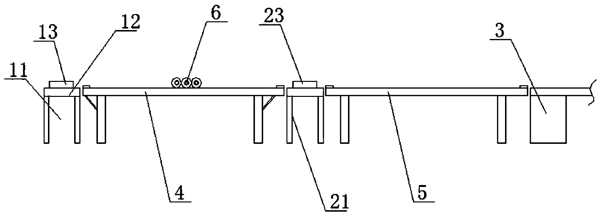
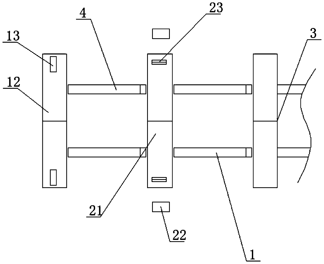
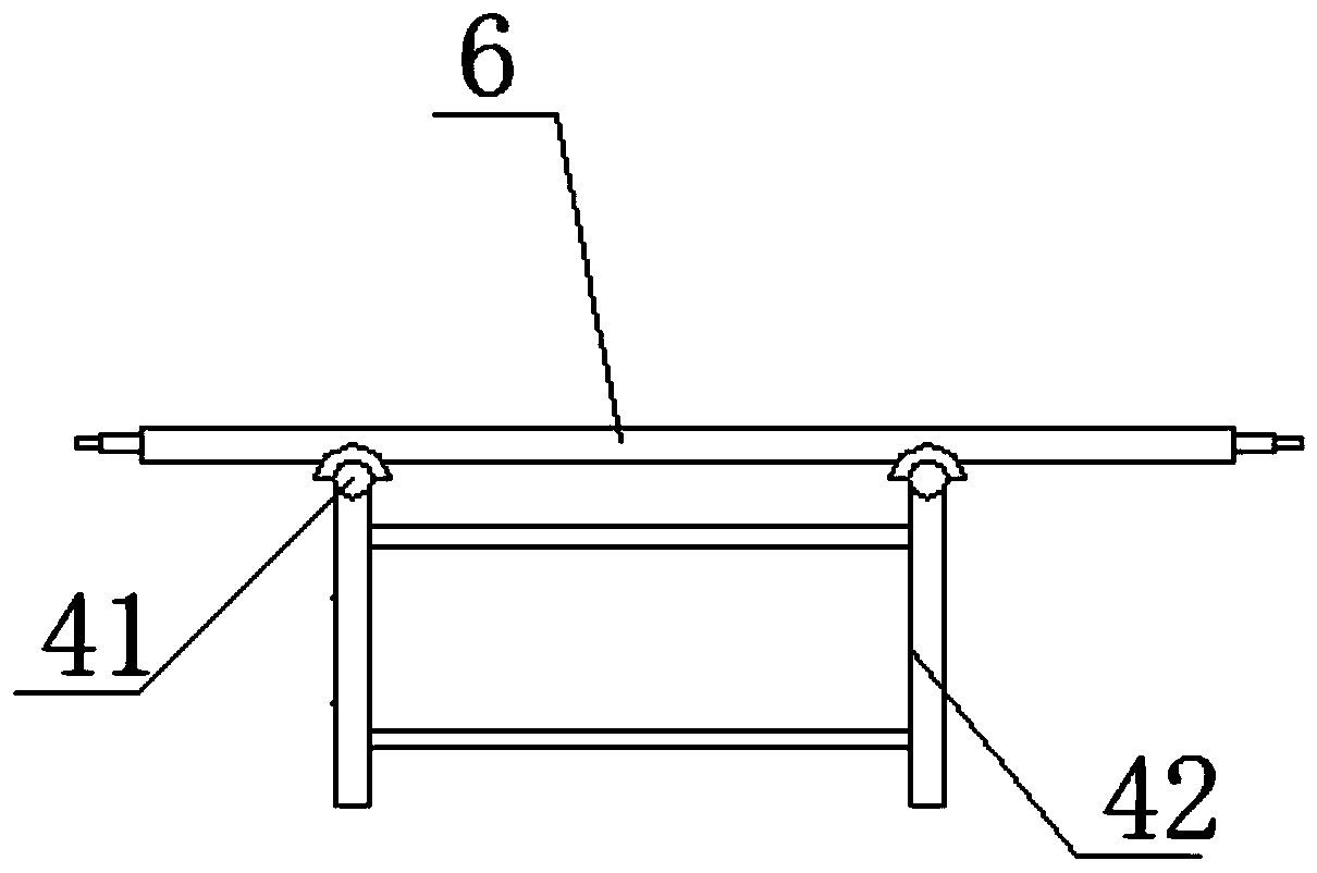
[0050] The roller body 6 preparation device of this embodiment includes: a shaft head installation device 1, a shaft head welding device 2 and a polishing device 3 arranged at intervals; specifically, the shaft head installation device 1 includes a first frame 11, located on The working platform 12 on the first frame 11, the roller shaft mounting seat 13 that is arranged on the supporting seat of the roller body 6 of the working platform 12 and the two ends of the supporting seat of the roller body 6; the axle head welding equipment 2 includes the second frame 21, And the welding workbench 22 located at the end of the second frame 21, the second frame 21 is provided with a supporting part 23 for placing the roller body 6, and the supporting part 23 can drive the roller body 6 to rotate.

[0051] The flow table a4 between the shaft head installation equipment 1 and the shaft head welding equipment 2; the flow table b5 between the shaft head welding equipment 2 and the polishing ...


PUM


Abstract

The invention relates to a roller body manufacturing device and technology. The roller body manufacturing device comprises shaft head installing equipment, shaft head welding equipment, polishing equipment, a circulation table a and a circulation table b, wherein the shaft head installing equipment, the shaft head welding equipment and the polishing equipment are arranged at intervals, the circulation table a is arranged between the shaft head installing equipment and the shaft head welding equipment, and the circulation table b is arranged between the shaft head welding equipment and the polishing equipment. Roller bodies are arranged on the circulation table a and the circulation table b in a single layer manner and move in the manner of rotating by themselves. The height difference between the circulation table a and the circulation table b and the equipment at the two ends is no more than 0.5 m. The roller bodies are moved through the circulation tables, the roller bodies are assembled by the adoption of the form of an assembly line, the roller bodies are arranged on the circulation tables in a single layer manner and move in the manner of rotating by themselves, the roller bodies are automatically transferred to the next working procedure on the circulation tables one by one or in batches, the roller bodies arranged in a single layer manner can be distinguished easily, workers can detect whether the surfaces of the roller bodies are damaged or scratched conveniently, and the workers can distinguish the machining batches of the roller bodies conveniently.

Description

technical field [0001] The invention relates to the technical field of composite pipe preparation, in particular to a roll body preparation device and process. Background technique [0002] The main feature of the roller body is that it is composed of three parts: the shaft head, the shaft and the roller at both ends. During the preparation, after the shaft head and the roller are assembled by interference, the welding seam reserved at the connection between the shaft head and the roller needs to be welded. To meet and ensure the force and or airtightness of the roller, and then polish the required roller body, the existing production process has the following problems: [0003] Since the roller body can be applied to many downstream equipment, such as ironing machine, cloth spreading machine, cloth feeding machine, folding machine, stacker and other linen finishing equipment, the roller body is required, and each equipment needs There are several types of roll bodies, so t...

Claims


Application Information

Patent Timeline
Patent Type & Authority Applications(China)
IPC IPC(8): B23P23/00
CPCB23P23/00
Inventor 高毓成
Owner SHANDONG GUANGTAI ENVIRONMENTAL TECH CO LTD
Why Eureka
Try Eureka