
Grate closed-die forging technology and forming closed die

A grating bar closed-type, die forging technology, applied in the field of sintering forging, can solve the problems of harsh working conditions of grate bars, increase of grate bars, wearing parts, etc., and achieve the effect of improving product quality and production efficiency and reducing material costs

Pending Publication Date: 2019-11-05
中机精密成形产业技术研究院(安徽)股份有限公司
View PDF0 Cites 2 Cited by
  • Summary
  • Abstract
  • Description
  • Claims
  • Application Information

AI Technical Summary

Problems solved by technology

[0008] For this reason, the embodiment of the present invention provides a grate bar closed die forging process and forming closed die, which solves the problems of the existing grate bar with poor working conditions, complicated damage causes, vulnerable parts, and the length of service life of the grate bar. It directly affects the production rate of the sintering machine and the production cost of the sintering ore. With the increase of the annual output of the sintering ore, the consumption of grates is gradually increasing.

Method used


Image

  • Grate closed-die forging technology and forming closed die
  • Grate closed-die forging technology and forming closed die
  • Grate closed-die forging technology and forming closed die

Examples


Embodiment 1

[0051] like figure 1 As shown, the embodiment of the present invention provides a kind of grate bar closed die forging process, comprises steps:

[0052] Step S100, blanking, selecting a bar according to the total length and projected area of ​​the forging blank;

[0053] The specific steps of bar calculation are as follows:

[0054] Step 101, making a three-dimensional graphic through UG according to the forging blank, and calculating the quality of the bar according to the three-dimensional image;

[0055] Step 102. Determine the length of the bar according to the cavity, and calculate the diameter of the bar according to the length and mass of the bar. The specific calculation process is:

[0056] m=ρV, V=πD 2 L / 4,

[0057] get: Among them, m is the quality of the blank, ρ is the density of the blank, V is the volume of the blank, D is the diameter of the bar, and L is the length of the blank;

[0058] Step 103. On the premise of determining the blanking length, enla...

Embodiment 2

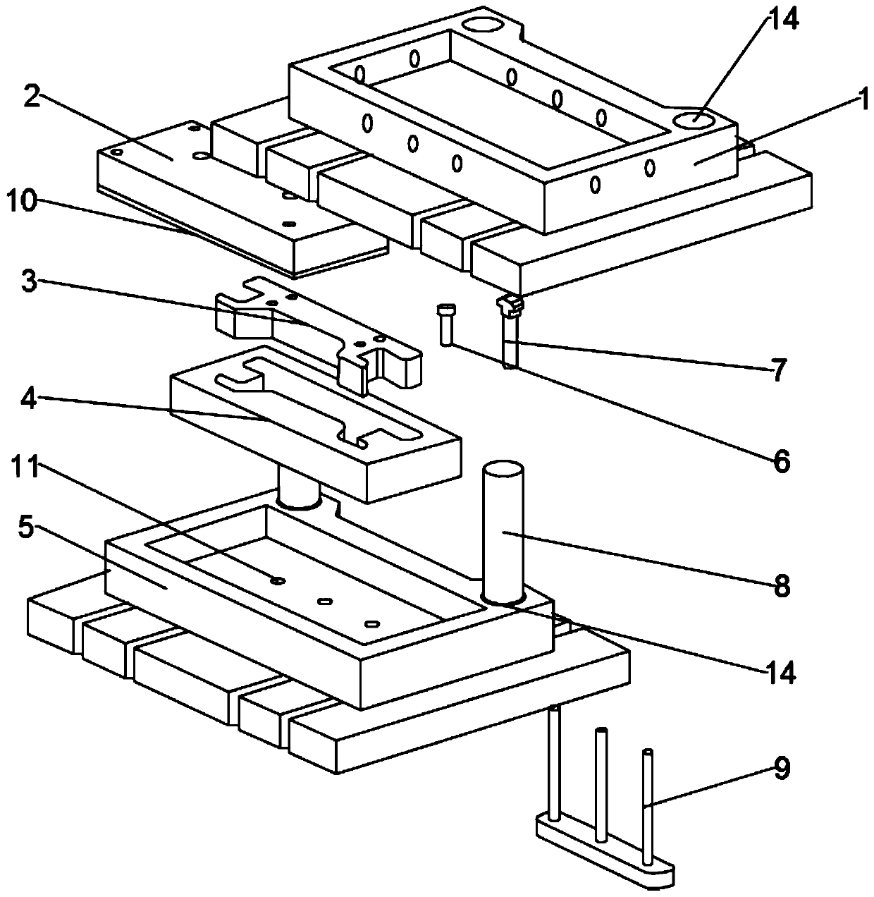
[0097] like Figure 1 to Figure 4 Shown, a kind of grate bar forming closed mold, comprises the upper die cover 1 that connects patrix and the lower die cover 5 that connects lower mold, and die 4 and convex film 3, is installed on the upper die cover 1 and is used for connecting upper die cover 1. The die set 1 and the fixing plate 2 of the punch 3 are used to connect the punch 3 and the upper die set 1. The punch 3 and the die 4 are generally made of H13 die steel. The plate connection can reduce the use of forming die materials and save the manufacturing cost of the whole set of dies.

[0098] And by setting the elastic pad 10 between the punch 3 and the fixed plate 2, a certain elastic buffer can be provided during the stamping process. The elastic pad 10 adopts a sheet-shaped structure made of H13 die steel material, and the sheet The cross-section of the shaped structure is arc-shaped, and the elastic structure formed by the superposition of several arcs, or the superim...


PUM


Abstract

The embodiment of the invention discloses a grate closed-die forging technology. The grate closed-die forging technology comprises the steps that material selecting and feeding are conducted; multi-stage medium frequency heating is conducted, and oxide skins are removed; a lubricant and a releasing agent are used, and bar stocks are put into a die after the die is preheated; and after the surfacesof the bar stocks are lubricated through the glass lubricant, the die is closed. The closed die is included and comprises an upper die sleeve connected with an upper die, a lower die sleeve connectedwith a lower die, a concave die and a convex die; the upper die sleeve is provided with a fixing plate for being connected with the upper die sleeve and the convex die, an elastic cushion is arrangedbetween the convex die and the fixing plate, and the convex die is installed on the fixing plate through a hold-down nut; the bottom of the lower die sleeve is provided with a plurality of ejector rods at equal intervals, through column holes for installing the ejector rods are formed in the lower die sleeve, and the edge of the periphery of the upper surface of the lower die sleeve is provided with an air compression groove, air inflation holes are formed in the position, at the bottom of the interior of the air compression groove, of the lower die sleeve, and the air inflation holes extendto the through column holes; and the structure strength of existing grates during forging is improved, and the number of times of forging in the forging process is decreased.

Description

technical field [0001] The embodiment of the present invention relates to the technical field of sintering forging, and in particular to a closed die forging process and a forming closed die for grating bars. Background technique [0002] The grate bar is the main accessory on the trolley of the sintering machine. The function of the grate bar is to form a groove-shaped space with the trolley railing to accommodate and carry mineral materials. The part of the grate bar in contact with the mineral material is the upper surface, and the two ends of the upper part of the grate bar are stressed to play a supporting role. The bottom of the grate bar has two functions. First, it is used to fix the grate bar when it is turned over and unloaded so that it cannot fall off; secondly, it plays a supporting role when the top of the grate bar is under pressure, which can effectively prevent the grate bar from falling off. bending; [0003] And existing grating bar adopts ferritic stain...

Claims


Application Information

Patent Timeline
Patent Type & Authority Applications(China)
IPC IPC(8): B21J5/02B21J13/02
CPCB21J5/025B21J13/02
Inventor 朱振松朱经晨丁金根边翊
Owner 中机精密成形产业技术研究院(安徽)股份有限公司
Learn More