


Quick Research
Generate reliable direction feasibility study reports for your R&D in just a few steps.

Technical Q&A
Discover and master advanced knowledge NOW. Basics, ideas, possibilities, all at once.

Find Solutions
As an expert in R&D theories, this can generate solutions to your technical problems instantly.

Evaluate Feasibility
Analyze your overall solution with one click, know your potential R&D risks in advance.

Monitor Landscape
Get weekly tech updates, stay abreast of the latest tech innovations and key insights.
Beam dyeing penetration detection device
A technique of penetrant detection and warp beam dyeing, which is applied in the field of warp beam dyeing penetrant detection devices, can solve the problems of poor beam burst rate control and low efficiency, and achieve the effects of easy promotion, low cost and simple structure
- Summary
- Abstract
- Description
- Claims
- Application Information
AI Technical Summary
Problems solved by technology
Method used
Image

Examples
Embodiment Construction
[0018] Below in conjunction with accompanying drawing, the present invention will be further described:
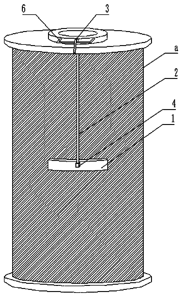
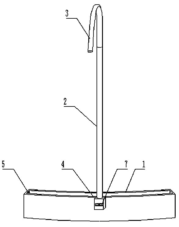
[0019] Such as figure 1 , figure 2 As shown, a warp beam dyeing penetration detection device of the present invention, the warp beam dyeing penetration detection device includes an arc-shaped groove 1, a connecting seat 4 is arranged in the center on the outer side of the arc-shaped groove 1, and a connecting seat 4 is arranged on the upper part of the connecting seat 4. Rod 2, the top of the connecting rod 2 is provided with a "u" handle 3; the arc groove 1 is provided with a scale 5; the length of the connecting rod 2 can be adjusted.
[0020] A level 7 is arranged outside the connecting seat 4 .
[0021] The inner side of the arc-shaped groove 1 is made of soft material.
[0022] The "u"-shaped handle 3, the connecting seat 4 and the connecting rod 2 are respectively connected by threads.
[0023] Scale scales 5 are arranged around the inside of the arc-shaped groo...
PUM
 Abstract
Description
Claims
Application Information
 - R&D Engineer
- R&D Manager
- IP Professional
- Industry Leading Data Capabilities
- Powerful AI technology
- Patent DNA Extraction
Browse by: Latest US Patents, China's latest patents, Technical Efficacy Thesaurus, Application Domain, Technology Topic, Popular Technical Reports.
© 2024 PatSnap. All rights reserved.Legal|Privacy policy|Modern Slavery Act Transparency Statement|Sitemap|About US| Contact US: help@patsnap.com