


Quick Research
Generate reliable direction feasibility study reports for your R&D in just a few steps.

Technical Q&A
Discover and master advanced knowledge NOW. Basics, ideas, possibilities, all at once.

Find Solutions
As an expert in R&D theories, this can generate solutions to your technical problems instantly.

Evaluate Feasibility
Analyze your overall solution with one click, know your potential R&D risks in advance.

Monitor Landscape
Get weekly tech updates, stay abreast of the latest tech innovations and key insights.
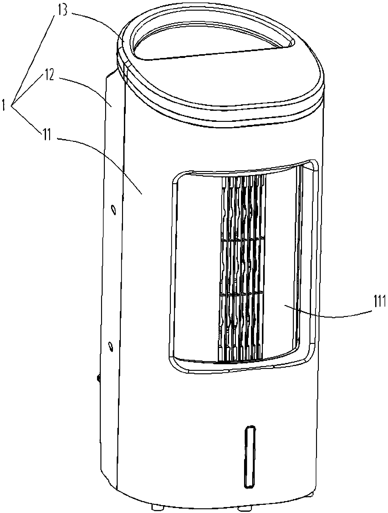
Air duct rotating structure of air conditioner fan and air conditioner fan
A technology of rotating structure and air-conditioning fan, which is applied in air-conditioning systems, space heating and ventilation, heating and ventilation hoods/covers, etc. It can solve the problems of complex structure of air guide, unsightly appearance, and many production processes. Achieve the effect of enhancing experience, simple structure and simple production process
- Summary
- Abstract
- Description
- Claims
- Application Information
AI Technical Summary
Problems solved by technology
Method used
Image

Examples
Embodiment Construction
[0061] The technical solutions of the present invention will be clearly and completely described below in conjunction with the accompanying drawings. Apparently, the described embodiments are some of the embodiments of the present invention, but not all of them. Based on the embodiments of the present invention, all other embodiments obtained by persons of ordinary skill in the art without making creative efforts belong to the protection scope of the present invention.
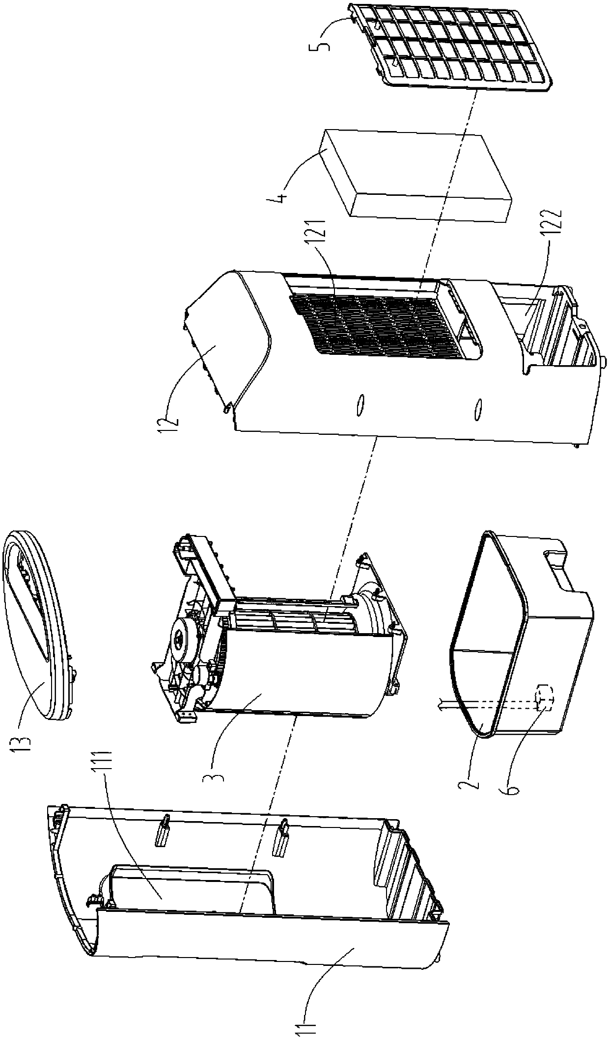
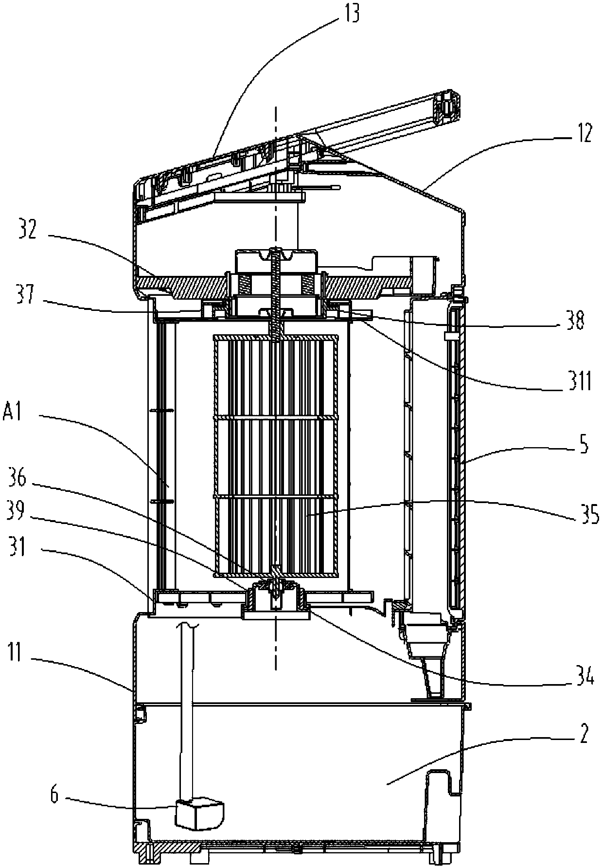
[0062] Such as Figure 4 As shown, the present invention provides a rotating structure 3 for an air conditioner fan duct, comprising: a rotating cover 31, a motor bracket 32, a support seat 34, an air supply fan wheel 35 and a gear transmission 37, and the upper and lower parts of the rotating cover 31 A rotating upper cover 311 and a rotating lower cover 312 fixedly connected thereto are respectively provided with an air outlet A1 and an air inlet A2 on the rotating cover 31, as Figure 5Shown; Wherein the m...
PUM
 Abstract
Description
Claims
Application Information
 - R&D Engineer
- R&D Manager
- IP Professional
- Industry Leading Data Capabilities
- Powerful AI technology
- Patent DNA Extraction
Browse by: Latest US Patents, China's latest patents, Technical Efficacy Thesaurus, Application Domain, Technology Topic, Popular Technical Reports.
© 2024 PatSnap. All rights reserved.Legal|Privacy policy|Modern Slavery Act Transparency Statement|Sitemap|About US| Contact US: help@patsnap.com