Coated rolling element bearing

A technology for rolling elements and bearings, applied to bearings, rotating parts that resist centrifugal force, bearing components, etc., can solve problems such as coating peeling, and achieve the effects of low coating temperature, low friction, and high anti-wear performance

Inactive Publication Date: 2003-03-26
SKF ENG & RES CENT
View PDF4 Cites 0 Cited by
  • Summary
  • Abstract
  • Description
  • Claims
  • Application Information

AI Technical Summary

Problems solved by technology

In plain bearings, the adhesion of diamond-like carbon coatings to the substrate is sufficient, however, in rolling element bearings, such coatings will flake off due to the high contact stresses in rolling element bearings

Method used


Image

  • Coated rolling element bearing
  • Coated rolling element bearing
  • Coated rolling element bearing

Examples


Embodiment Construction

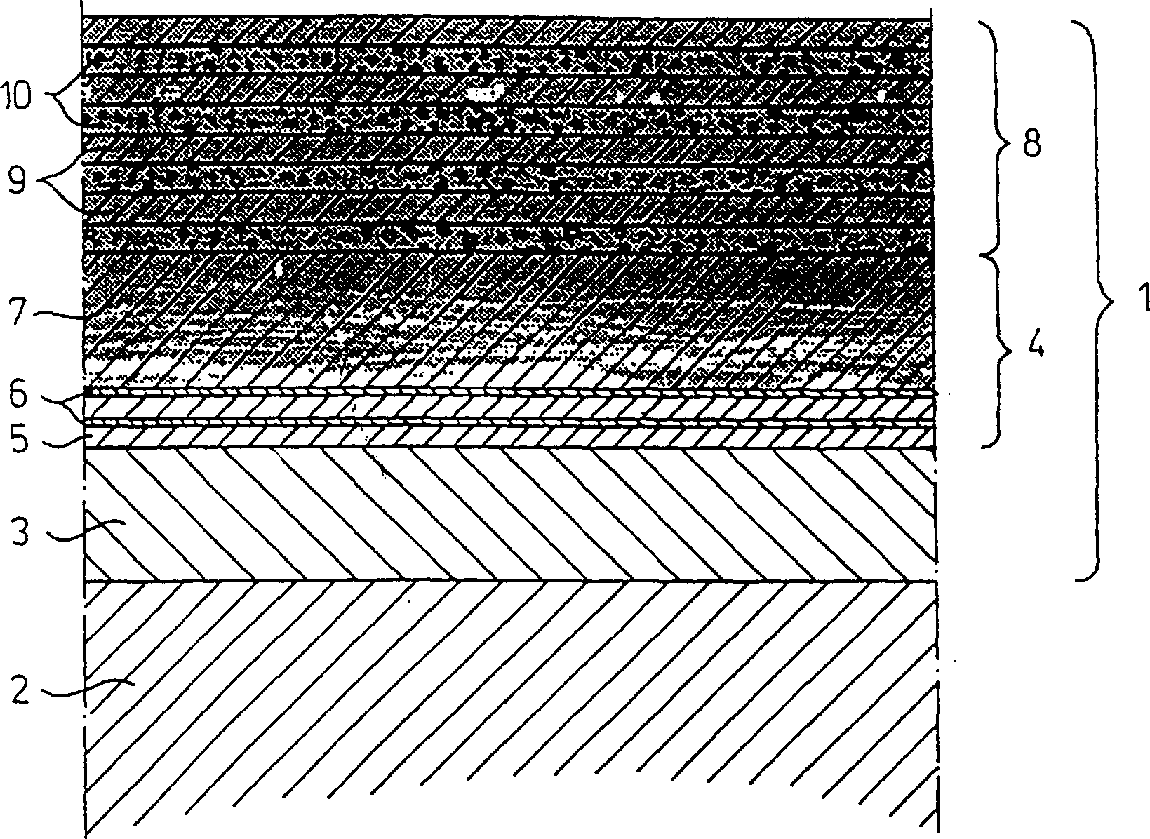
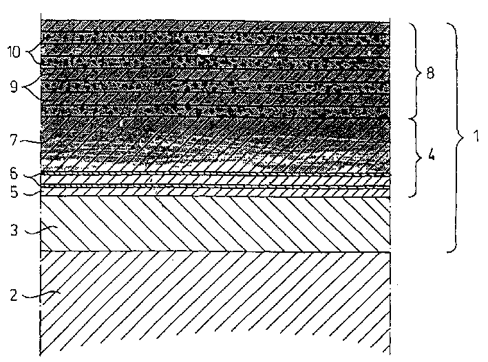
[0026] figure 1 Shows a cross-sectional view of the rolling elements of a rolling element bearing or the outer layer of the raceway of a ring. The entire exterior is generally indicated with reference numeral 1 and is applied to a substrate 2, for example bearing steel.

[0027] Said entire exterior 1 comprises an intermediate metallic interlayer 3 applied directly to the substrate 2, a transition zone 4 following the intermediate metallic interlayer 3, and a metal-mixed-diamond-like carbon coating 8. The transition region 4 comprises a multilayer transition region obtained by alternating metal carbide layers 5 and metal layers 6 . Subsequently, towards the multilayer structure 8 , a smooth transition region 7 results. The transition region 7 provides a smooth transition from metal carbide to a mixture of metal carbide and diamond-like carbon. The multilayer structure 8 comprises alternating metal carbide layers 9 and diamond-like carbon layers 10 .

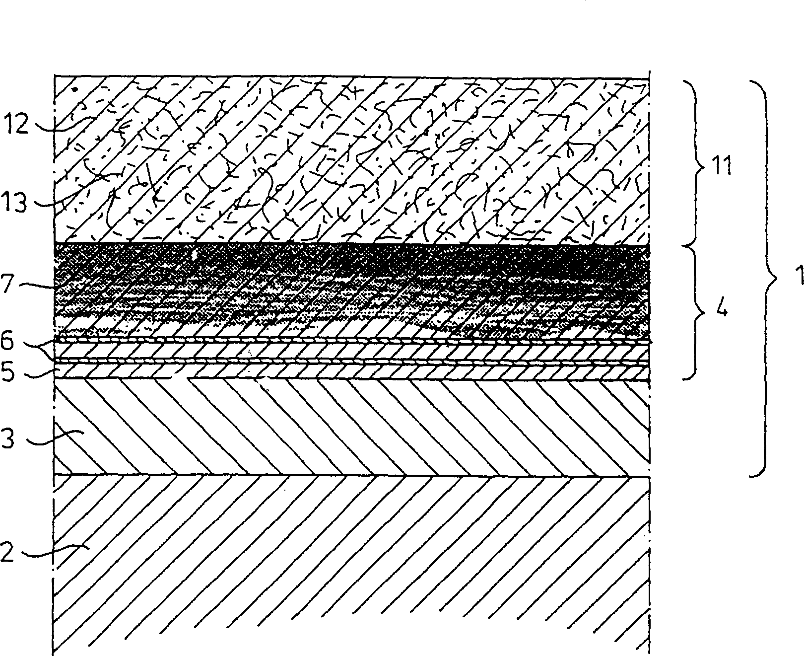
[0028] figure 2 A c...


PUM

PropertyMeasurementUnit
thicknessaaaaaaaaaa
sizeaaaaaaaaaa

Abstract

A rolling element bearing, comprises an inner ring, an outer ring and rolling elements which are in rolling contact with the raceways of the inner ring and the outer ring. The rolling elements and / or the raceway (2) of at least one of the rings is coated with a metal-mixed diamond-like carbon layer (8).

Description

technical field [0001] The invention relates to the field of rolling element bearings, in particular to rolling element bearings with coating. Background technique [0002] Rolling element bearings are used in a variety of different environments. As long as lubrication can be ensured, they can generally achieve their normal design life. [0003] However, under poor or borderline lubrication conditions, the behavior of rolling element bearings is not very favorable. In such cases, it may prove impossible to form a lubricating film that would result in direct metal-to-metal contact between the rolling elements and the rings, leading to problems such as adhesive wear, galling and premature failure occur. [0004] Furthermore, rolling element bearings often exhibit a phenomenon known as "pseudo-friction erosion" when exposed to vibrational or oscillating motion phases without rotational motion under static loads, which also limits bearing performance. lifespan. [0005] As ...

Claims


Application Information

Patent Timeline
Patent Type & Authority Patents(China)
IPC IPC(8): F16C33/04F16C33/06F16C33/16F16C33/30F16C33/62F16C33/64
CPCF16C33/30F16C2206/04F16C33/62F16C2240/64Y10T428/24975
Inventor 斯图尔特·亚历山大·莱斯利·霍顿雷尼尔·奥尔加·恩斯特·维基根罗宾·托马斯·坎迪尔汉斯·舍斯特伦
Owner SKF ENG & RES CENT
Why Eureka
Try Eureka