
Telescopic structure of crane

A telescopic and crane technology, which is applied in the direction of cranes, walking bridge cranes, load hanging components, etc., can solve the problems of crane running track interference, poor adjustment performance of handling work, and affecting the stable movement of telescopic beams, etc., to achieve improved stability sexual effect

Pending Publication Date: 2019-10-29
江阴帕沃特起重机械有限公司
View PDF0 Cites 0 Cited by
  • Summary
  • Abstract
  • Description
  • Claims
  • Application Information

AI Technical Summary

Problems solved by technology

[0003] When the existing overhead cranes perform cross-area horizontal transport operations, they generally complete the corresponding process on one station, and then use another transport method to transport the product to the other station. The running track of the crane in the area is fixed. When moving the product from one side of the station to the other side, it is usually necessary to use another method of transportation to move the product to the other side of the station, but other handling devices may affect the crane. The running track causes interference and is limited by the site. All connections of the traditional flexible KBK are flexible connections, which can only carry downward loads and cannot carry upward reverse loads. The telescopic structures of some cranes in the prior art are in telescopic beam When the load is elongated, the unloaded end will cause the drive wheel to be air-pressed under the gravity of the load, which will affect the stable movement of the telescopic beam, resulting in poor adjustment performance of the handling work

Method used


Image

  • Telescopic structure of crane
  • Telescopic structure of crane
  • Telescopic structure of crane

Examples


Embodiment Construction

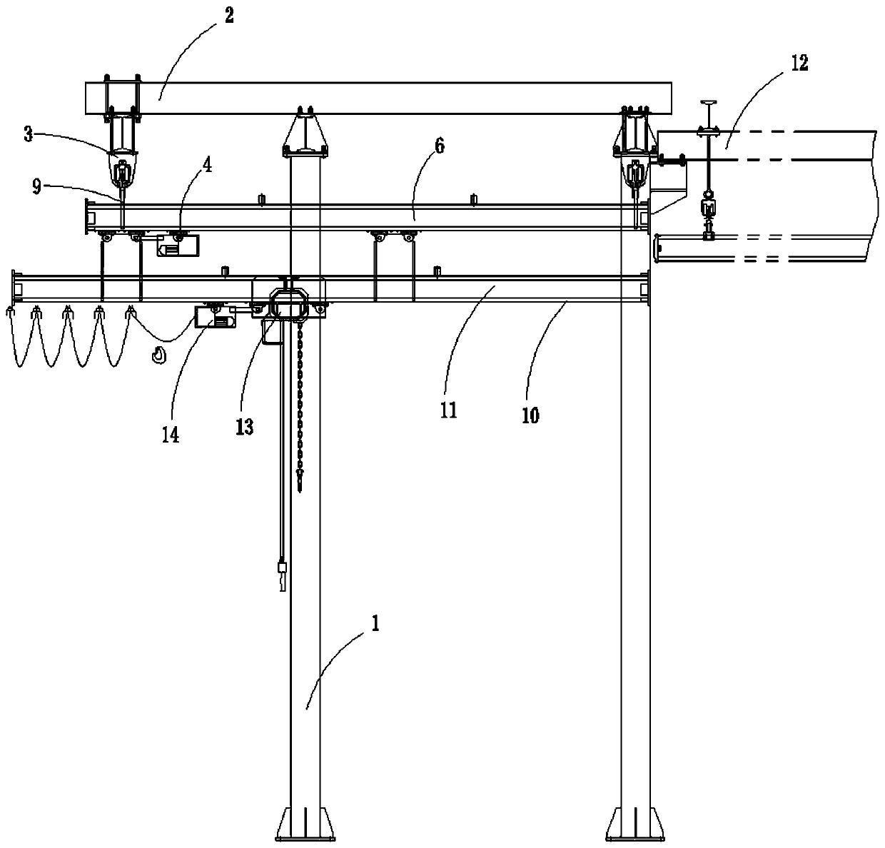
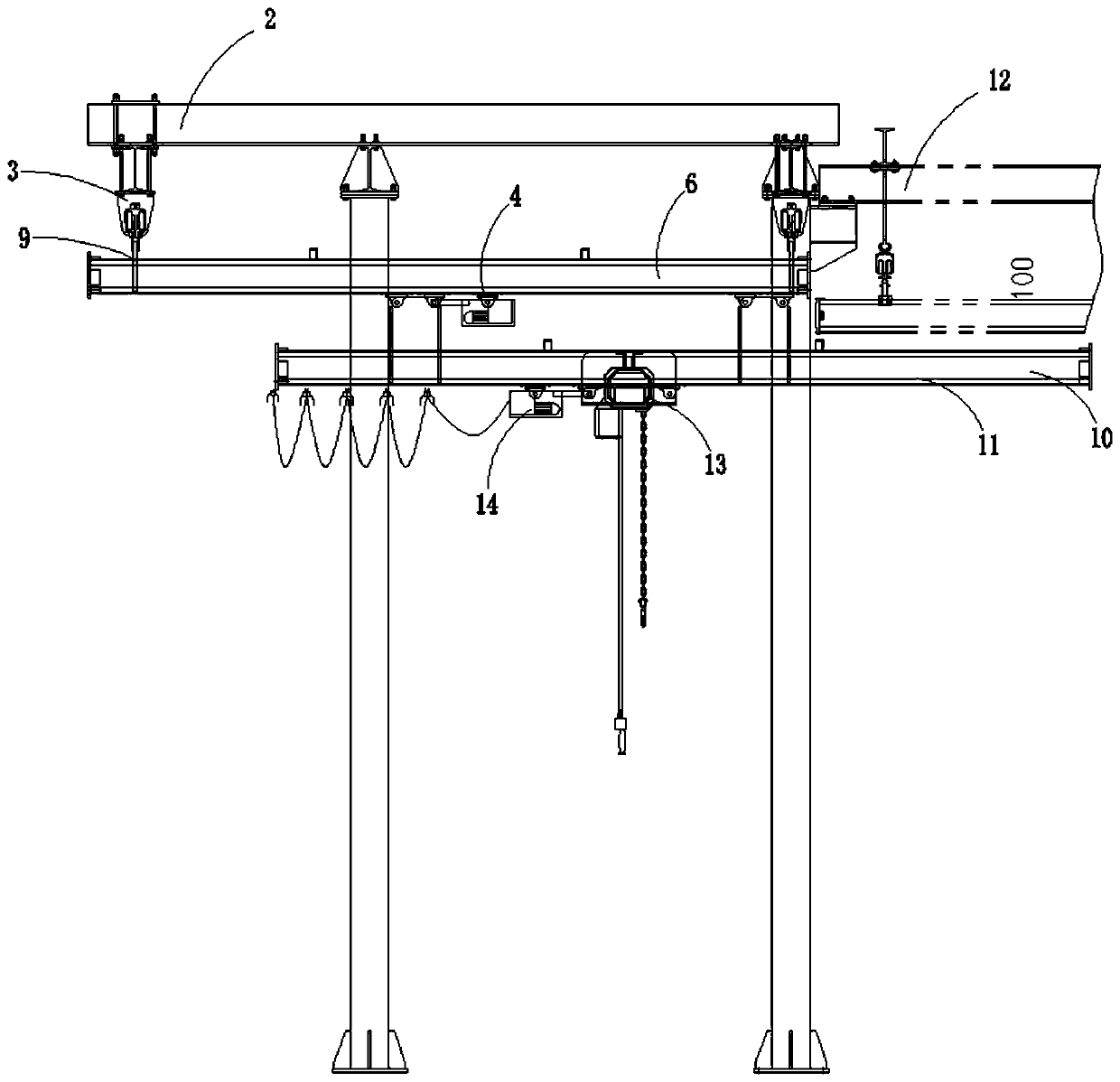
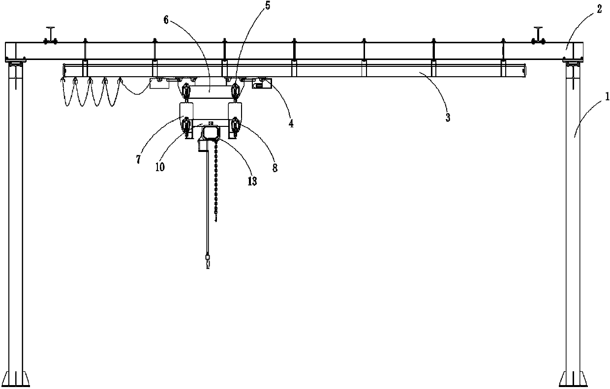
[0029] like Figure 1 to Figure 4 Telescoping structure of the crane shown, including

[0030] Column 1, set on the ground;

[0031] The steel beam 2 is connected to the top of the column 1;

[0032] The first guide rail 3 is symmetrically arranged on the bottom of the steel beam 2;

[0033] The first drive wheel 4 is arranged on the first guide rail 3;

[0034] The balance beam 6 is arranged directly under the steel beam 2, and is connected to the first driving wheel 4 through the first connecting frame 9;

[0035] The second guide rail 7 is arranged at the lower end of the balance beam 6;

[0036] The second driving wheel 8 is arranged on the second guide rail 7;

[0037] The telescopic beam 10 is arranged below the balance beam 6 and is connected to the second driving wheel 8 through the second connecting frame,

[0038] The third guide rail 11 is arranged at the lower end of the telescopic beam 10;

[0039] The hoisting device is arranged on the third guide rail 11;...


PUM


Abstract

The invention discloses a telescopic structure of a crane. The structure comprises a stand column, a steel beam connected to the top end of the stand column, first guide rails symmetrically arranged at the bottom of the steel beam, a first driving wheel arranged on the first guide rails, a balance beam arranged under the steel beam and connected with the first driving wheel through a first connecting frame, a second guide rail arranged at the lower end of the balance beam, a second driving wheel arranged on the second guide rail, a telescopic beam arranged below the balance beam and connectedwith the second driving wheel through a second connecting frame, and a third guide rail arranged at the lower end of the telescopic beam. According to the telescopic structure of the crane, a traditional flexible KBK rail is transformed into a telescopic type so that the telescopic structure can be conveniently applied to occasions limited by places. When one side of the telescopic beam is extended for hoisting, the other side of the telescopic beam abuts against the first driving wheel and a second driving wheel axle by an assembled rolling shaft, so that the problem of empty wheel pressure caused by warping of the first driving wheel and the second driving wheel is solved, and the stability of load carrying adjustment is improved.

Description

technical field [0001] The invention relates to a telescopic structure of a crane, which belongs to the technical field of cranes. Background technique [0002] The bridge crane is a lifting device that is placed horizontally over the workshop, warehouse and stockyard for material lifting; because its two ends are located on tall cement columns or metal supports, it is shaped like a bridge; the bridge frame of the bridge crane is laid along the The tracks on the elevated sides on both sides run longitudinally, which can make full use of the space under the bridge frame to lift materials without being hindered by ground equipment; it is a kind of hoisting machinery with the widest range of use and the largest number. [0003] When the existing overhead cranes perform cross-area horizontal transport operations, they generally complete the corresponding process on one station, and then use another transport method to transport the product to the other station. The running trac...

Claims


Application Information

Patent Timeline
IPC IPC(8): B66C17/00B66C7/00
CPCB66C17/00B66C7/00
Inventor 樊晟吴演哲吴枝远吴枭钱磊
Owner 江阴帕沃特起重机械有限公司
Learn More