
Motor vibration control method and device and computer readable storage medium

A motor, steady-state vibration technology, applied in the direction of AC motor control, control system, electrical components, etc., can solve the problem of decreased experience satisfaction, large user lag, etc., to shorten the acceleration time, reduce the effect of lag

Pending Publication Date: 2019-10-25
AAC TECH PTE LTD
View PDF4 Cites 21 Cited by
  • Summary
  • Abstract
  • Description
  • Claims
  • Application Information

AI Technical Summary

Problems solved by technology

[0003] Vibration feedback is realized based on the excitation signal to excite the motor vibration in the terminal. At present, in the related art, a steady-state voltage signal of a specific period is usually used to excite the motor to vibrate. The motor will go through an acceleration process in the early stage of the vibration response to achieve Steady-state vibration, and then continue the steady forced steady-state motion after reaching the steady-state vibration until the end of the signal period, so in this case, there is a certain buffering process in the early vibration response of the motor, which will bring greater impact to the user. The sense of lag, leading to a decline in experience satisfaction

Method used


Image

  • Motor vibration control method and device and computer readable storage medium
  • Motor vibration control method and device and computer readable storage medium
  • Motor vibration control method and device and computer readable storage medium

Examples


Embodiment Construction

[0031] In order to make the purpose, features and advantages of the present invention more obvious and understandable, the technical solutions in the embodiments of the present invention will be clearly and completely described below in conjunction with the accompanying drawings in the embodiments of the present invention. Obviously, the described The embodiments are only some of the embodiments of the present invention, but not all of them. Based on the embodiments of the present invention, all other embodiments obtained by those skilled in the art without making creative efforts belong to the protection scope of the present invention.

[0032] In order to solve the defect in the related art that when the motor is excited to vibrate with a steady-state voltage signal of a specific period, there is a certain buffering process in the early vibration response of the motor, and the user perceives a relatively large lag in the vibration, the first embodiment of the present inventio...


PUM


Abstract

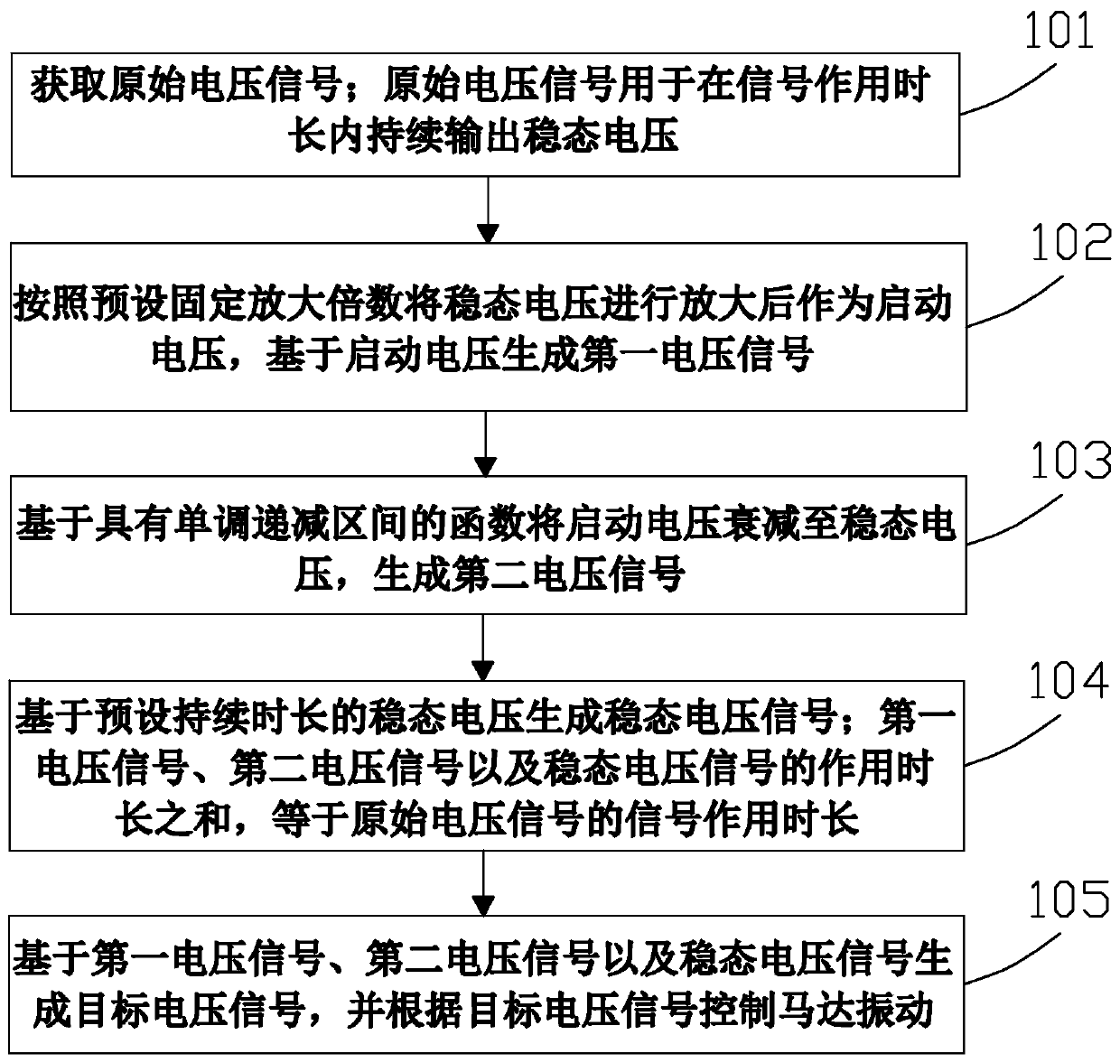
The invention provides a motor vibration control method and device and a computer readable storage medium. The method comprises the steps: amplifying a steady-state voltage to generate a first voltagesignal for controlling the accelerated vibration of a motor to a target vibration amplitude lower than the steady-state vibration amplitude; attenuating a starting voltage to the steady-state voltageto generate a second voltage signal for controlling the motor to vibrate from the target vibration amplitude to the steady-state vibration amplitude; generating a steady-state voltage signal used forcontrolling steady-state vibration of the motor based on the steady-state voltage with the preset duration; and finally controlling the motor to vibrate through the target voltage signal generated bythe first voltage signal, the second voltage signal and the steady-state voltage signal. Through the implementation of the invention, the steady-state voltage is amplified to be used as the excitation voltage of the motor vibration acceleration section, and then the excitation voltage is stably reduced to the steady-state voltage, so that the acceleration time of the motor vibration response in the early stage is effectively shortened, and the hysteresis feeling of the motor vibration feedback to a user is reduced.

Description

【Technical field】 [0001] The present invention relates to the technical field of electronic equipment, in particular to a motor vibration control method, device and computer-readable storage medium. 【Background technique】 [0002] Today, with the rapid development of science and technology, various electronic terminals have been widely used in users' daily life and work. In order to improve user experience, R&D personnel in various fields are also constantly pursuing to improve product performance. Among them, vibration feedback is a part of the terminal. It is a typical application, and it is a factor that cannot be ignored in improving the user experience of the terminal. [0003] Vibration feedback is realized based on the excitation signal to excite the motor vibration in the terminal. At present, in the related art, a steady-state voltage signal of a specific period is usually used to excite the motor to vibrate. The motor will go through an acceleration process in the ...

Claims


Application Information

Patent Timeline
IPC IPC(8): H02P25/032
CPCH02P25/032
Inventor 郑亚军向征桑成艳
Owner AAC TECH PTE LTD
Learn More