
Power supply support system of high-voltage switch cabinet

A high-voltage switchgear and power supply technology, applied in emergency power supply arrangements, substations/switchgear boards/panels/desks, electrical components, etc., can solve the inconvenience of operation and maintenance and power supply services, UPS cannot supply power, and circuit breakers cannot automatically reclose gate etc.

Pending Publication Date: 2019-10-25
HAIHONG ELECTRIC CO LTD
View PDF0 Cites 1 Cited by
  • Summary
  • Abstract
  • Description
  • Claims
  • Application Information

AI Technical Summary

Problems solved by technology

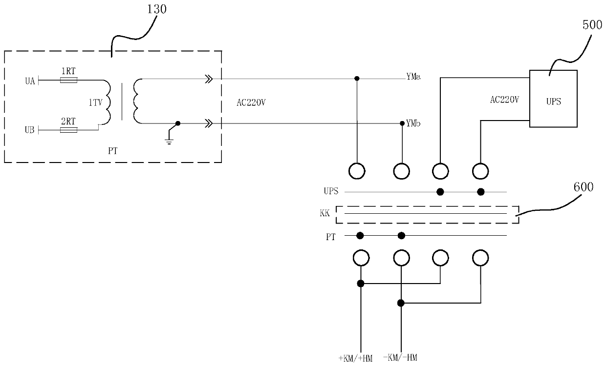
[0002] After a power failure, in order to maintain electric operation and relay protection, the high-voltage switchgear often needs to be equipped with UPS or DC screen; and the price of UPS is relatively cheap, so it is welcomed by the market; but if the power failure time exceeds the power supply of UPS Time, when the utility power comes in, the circuit breaker will not reclose automatically; because of cost issues, low-capacity voltage transformers are generally used in high-voltage switchgear, but low-capacity voltage transformers cannot provide power for a long time. Operation, relay protection and UPS power supply, so the power supply of UPS is supplied from the low-voltage side of the transformer through the air switch; therefore, even if the mains power comes in, the low-voltage side of the transformer is not charged, resulting in the failure of the UPS to supply power, and the circuit breaker cannot automatically Reclosing, at this time, you need to bring your own generator to charge the UPS to restore power supply, which will bring inconvenience to operation and maintenance and power supply services

Method used


Image

  • Power supply support system of high-voltage switch cabinet
  • Power supply support system of high-voltage switch cabinet
  • Power supply support system of high-voltage switch cabinet

Examples


Embodiment Construction

[0017] In order to make the object, technical solution and advantages of the present invention clearer, the present invention will be further described in detail below in conjunction with the accompanying drawings and embodiments. It should be understood that the specific embodiments described here are only used to explain the present invention, not to limit the present invention.

[0018] It should be noted that, if there is no conflict, various features in the embodiments of the present invention may be combined with each other, and all of them are within the protection scope of the present invention. In addition, although the functional modules are divided in the schematic diagram of the device, and the logical order is shown in the flowchart, in some cases, the division of modules in the device or the sequence shown in the flowchart can be performed in different ways. or the steps described.

[0019] After a power failure, in order to maintain electric operation and relay...


PUM


Abstract

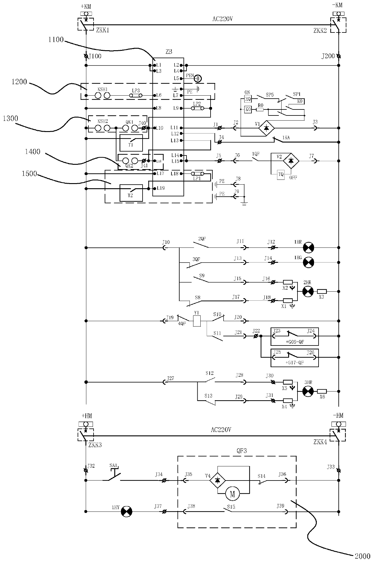
The invention discloses a power supply support system of a high-voltage switch cabinet. A wire inlet cabinet comprises a wire inlet voltage transformer, a wire inlet current transformer and a first breaker module, the wire inlet voltage transformer, the wire inlet current transformer and the first breaker module are connected in sequence, the first breaker module is connected with a metering cabinet through a high-voltage bus bar, the wire outlet cabinet comprises a second circuit breaker module, a wire outlet current transformer and a second zero-sequence current transformer which are connected in order the second breaker module is connected with the metering cabinet through the high-voltage bus bar, the second zero-sequence current transformer, the transformer and a UPS are connected inorder, the input end of a manual converter can be selectively connected to the secondary side of the wire inlet voltage transformer or the output side of the UPS, the output end of the manual converter is connected with a relay protector, the first circuit breaker module and the second circuit breaker module are controlled by a relay protector, power supply can be recovered without a self-providedgenerator, and the intelligent metering device is simple and convenient.

Description

technical field [0001] The invention relates to the field of electric equipment, in particular to a power supply protection system for a high-voltage switch cabinet. Background technique [0002] After a power failure, in order to maintain electric operation and relay protection, the high-voltage switchgear often needs to be equipped with UPS or DC screen; and the price of UPS is relatively cheap, so it is welcomed by the market; but if the power failure time exceeds the power supply of UPS Time, when the utility power comes in, the circuit breaker will not reclose automatically; because of cost issues, low-capacity voltage transformers are generally used in high-voltage switchgear, but low-capacity voltage transformers cannot provide power for a long time. Operation, relay protection and UPS power supply, so the power supply of UPS is supplied from the low-voltage side of the transformer through the air switch; therefore, even if the mains power comes in, the low-voltage si...

Claims


Application Information

Patent Timeline
Patent Type & Authority Applications(China)
IPC IPC(8): H02B1/30H02B1/20H02B1/04H02H7/22H02J9/06
CPCH02B1/30H02B1/20H02B1/04H02H7/22H02J9/06
Inventor 许凯旋翟丽珍于建军喻金曾光耀黄永华张小明
Owner HAIHONG ELECTRIC CO LTD
Learn More