
Optical detection system and method

An optical detection and light beam technology, applied in the optical field, can solve problems such as inadaptability, large influence of spectrum analysis method, and large noise interference, etc., and achieve the effects of strong practicability, simple deployment, and convenient operation

Active Publication Date: 2022-01-25
SHENZHEN LUBANG TECH CO LTD
View PDF7 Cites 0 Cited by
  • Summary
  • Abstract
  • Description
  • Claims
  • Application Information

AI Technical Summary

Problems solved by technology

For example, the scattered energy analysis method has a complex system, slow detection speed, and cannot determine the specific location of the defect; the spectrum analysis method is greatly affected by the deep structure of the defect, and cannot reflect the size of the surface layer of the defect; the interference fringes of the double-beam interference method are easy to drift, And it is not suitable for a variety of defect detection; the filter imaging method is aimed at imaging high-frequency components or low-frequency components in the spatial spectrum of the beam, which is greatly affected by noise interference

Method used


Image

  • Optical detection system and method
  • Optical detection system and method
  • Optical detection system and method

Examples


Embodiment 1

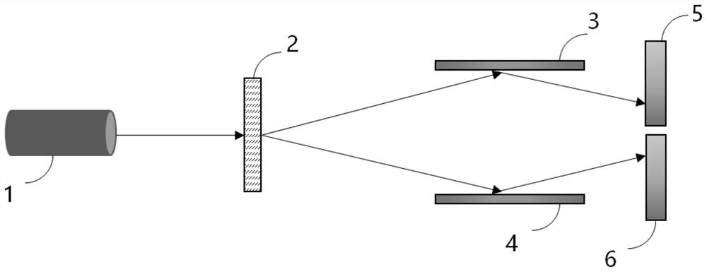
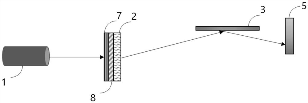
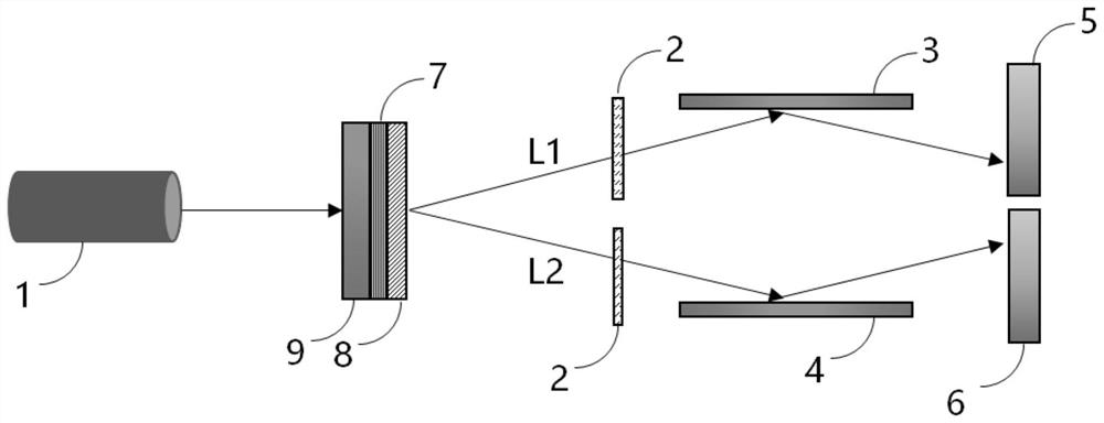
[0025] This embodiment discloses an optical detection system, including: a multispectral light source, a deflection device, and a data processing device.

[0026] Among them, the deflection device in this embodiment is located between the multi-spectral light source and the object to be measured, and is used to deflect the beams of different wavelengths emitted from the multi-spectral light source to directions corresponding to the wavelengths, and to deflect the light beams of different wavelengths The light beam is emitted to the object to be measured.

[0027] In this embodiment, the data processing device is used to: receive the light beam reflected by the surface of the object to be measured, and compare the reflected spectrum with the reference calibration spectrum reflected by the corresponding standard part to determine the wavelength of the difference, and then according to the difference Calculate the spatial coordinates corresponding to the surface defects of the ob...

Embodiment 2

[0039] Corresponding to the above embodiments, this embodiment discloses an optical detection method, including the following steps:

[0040] Step S1, setting a multi-spectral light source, and setting a deflection device between the multi-spectral light source and the object to be measured.

[0041] Step S2. The spectrum deflection device deflects the beams of different wavelengths emitted from the multi-spectral light source to directions corresponding to the wavelengths, and emits the deflected beams of different wavelengths to the object to be measured.

[0042] Step S3, receiving the light beam reflected by the surface of the object to be measured, and comparing the reflected spectrum with the reference calibration spectrum reflected by the corresponding standard part to determine the wavelength of the difference, and then calculate the to-be-measured wavelength according to the wavelength of the difference. The spatial coordinates corresponding to the surface defects of th...


PUM


Abstract

The invention relates to the field of optical technology, and discloses an optical detection system and method to quickly complete defect detection on the surface of an object. The system of the present invention includes: a multi-spectral light source; a deflection device located between the multi-spectral light source and the object to be measured, for deflecting the beams of different wavelengths emitted from the multi-spectral light source to directions corresponding to the wavelengths on, and emit the deflected light beams of different wavelengths to the object to be measured; the data processing device is used to receive the light beam reflected by the surface of the object to be measured, and compare the reflection spectrum with the reference calibration spectrum reflected by the corresponding standard part Spectral difference comparison is performed to determine the wavelength of the difference, and then the spatial coordinates corresponding to the surface defects of the object to be measured are calculated according to the wavelength of the difference.

Description

technical field [0001] The invention relates to the field of optical technology, in particular to an optical detection system and method. Background technique [0002] With the development of modern industrial technology, the requirements for high-precision processing technology are getting higher and higher. At the same time, surface inspection has become an indispensable part of industrial development, which reflects a country's industrial development level to a certain extent. [0003] Surface detection usually uses the changes of heat, sound, light, electricity, magnetism and other reactions caused by abnormal material surface structure or defects or foreign objects, and uses physical or chemical methods as means, with the help of modern technology and equipment, to detect the surface defects of the tested parts ( or foreign matter) to detect the type, nature, quantity, shape, position, size, distribution and changes thereof. [0004] Traditional optical surface defect ...

Claims


Application Information

Patent Timeline
Patent Type & Authority Patents(China)
IPC IPC(8): G01N21/93G01N21/88G01N21/21G01N21/55
CPCG01N21/93G01N21/88G01N21/21G01N21/55G01N2021/216
Inventor 陈琪张礼朝李晓春
Owner SHENZHEN LUBANG TECH CO LTD
Learn More