
A die-casting mold

A die-casting mold and master mold technology, applied in the field of die-casting molds, can solve problems such as uncontrollable pouring of juice, long product repair time, and difficult metal separation, so as to reduce process time, save product follow-up processing process time, and improve injection molding. The effect of material speed

Active Publication Date: 2021-12-14
浙江寅寅科技有限公司
View PDF10 Cites 0 Cited by
  • Summary
  • Abstract
  • Description
  • Claims
  • Application Information

AI Technical Summary

Problems solved by technology

[0002] Most of the die-casting molds pour the molten juice into the mold cavity to die-cast the shape of the product, or pour it into the die-casting port of the mold and squeeze it into the mold cavity. Directly pouring the juice into the mold cavity for die-casting will produce a lot of burrs. It is mainly caused by the inability to control the amount of poured juice, and the method of hydraulically casting juice into the mold cavity is mostly to die-cast through the runner. This die-casting method needs to increase the gate so that the molten juice can quickly enter The mold cavity, but it is difficult to separate the product from the solidified metal of the runner, and needs to be cut and polished. This method results in a long time for product repair

Method used


Image

  • A die-casting mold
  • A die-casting mold
  • A die-casting mold

Examples


Embodiment 1

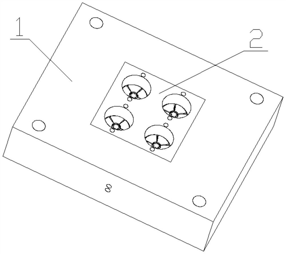
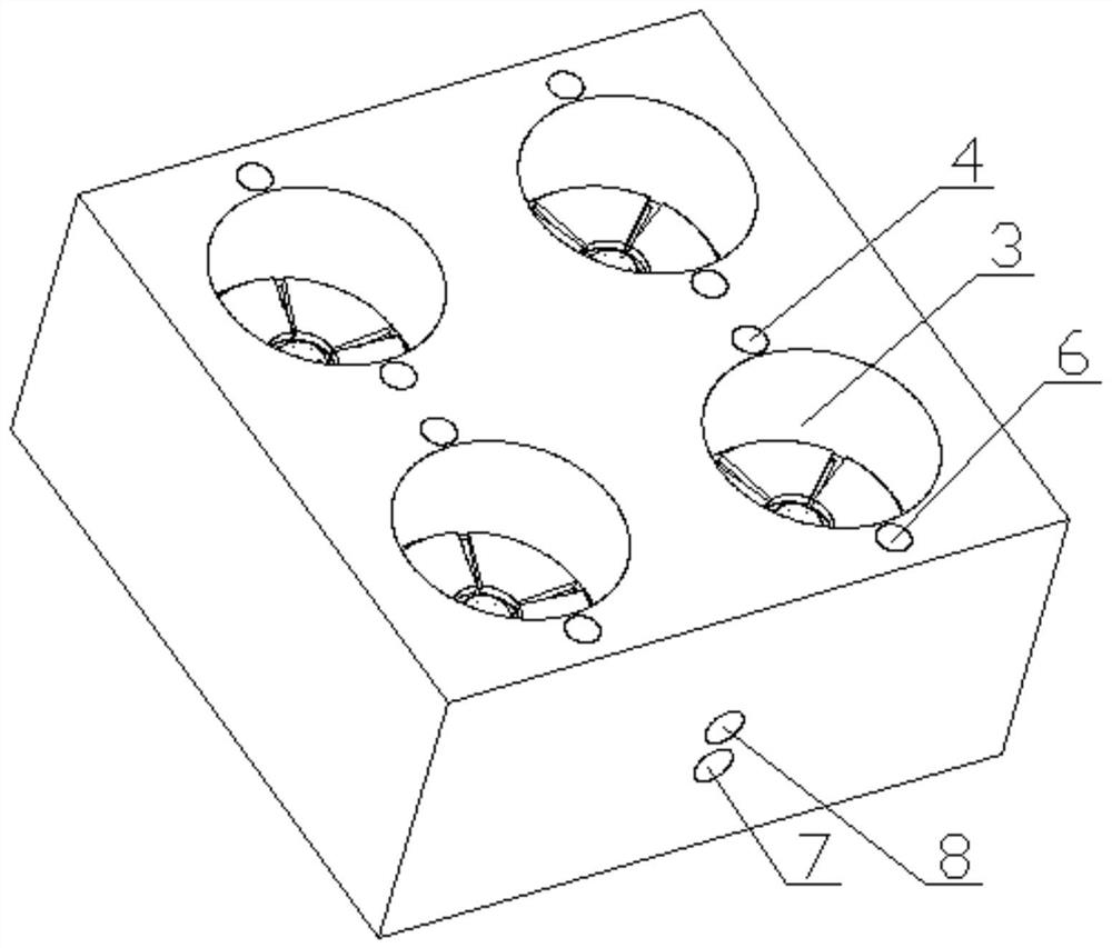
[0024] Such as figure 1 Shown; A kind of die-casting mold, comprises master template 1, is provided with master mold groove, liquid outlet hole and liquid inlet hole in described master template 1, is provided with master mold 2 in described master mold groove, and described master mold 2 is provided with a cooling liquid inlet hole 7 and a cooling liquid outlet hole 8, the cooling liquid inlet hole 7 and the cooling liquid outlet hole 8 are connected with the liquid outlet hole and the liquid inlet hole respectively, and the mother mold 2 is provided with There are several product forming mechanisms 3, one side of the product forming mechanism 3 is provided with a positioning demoulding hole 4, the positioning demoulding hole 4 is provided with a tailing separation mechanism 6, and the working end of the tailing separation mechanism 6 is connected to the The product forming mechanism 3 cooperates, and the cooling liquid inlet hole 7 and the cooling liquid outlet hole 8 are re...

Embodiment 2

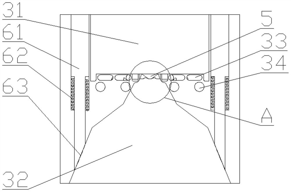
[0027] On the basis of Embodiment 1, the top point of the tapered cavity 51 is a vertical line perpendicular to the mother template 1, and the vertical line forms a maximum angle C with one side of the tapered cavity 51, and the vertical line and the cone The other side of the cavity 51 forms a minimum angle B, the degree of the angle C is 20 degrees to 70 degrees, and the degree of the angle B is 1 / 4 to 4 / 3 of the angle C; The degree of the angle C is 45 degrees to 55 degrees, and the degree of the angle B is 1 / 2 of the angle C; the injection hole 52 is elliptical, and the length of the ellipse is 0.3mm to 1.0mm; The injection mold cavity 32 is conical; the plurality of conical cavities 51 are arranged in a circle, and the sides of the largest angle C of the conical cavities 51 are arranged toward the center of the conical cavities 51 arranged in a circle; The mother mold 2 is provided with an exhaust groove for exhausting the molding cavity 31; one end of the injection ring ...


PUM

PropertyMeasurementUnit
angleaaaaaaaaaa
lengthaaaaaaaaaa

Abstract

The invention discloses a die-casting mold, which comprises a master template, a female mold groove, a liquid outlet hole and a liquid inlet hole are arranged in the female mold template, a female mold is arranged in the female mold groove, and a female mold is arranged on the female mold There are cooling liquid inlet holes and cooling liquid outlet holes, the cooling liquid inlet holes and cooling liquid outlet holes are respectively connected with the liquid outlet holes and the liquid inlet holes, and the master mold is provided with several product forming mechanisms. One side of the product molding mechanism is provided with a positioning demoulding hole, and a tailing material separation mechanism is arranged in the positioning demoulding hole, and the working end of the tailing material separation mechanism cooperates with the product forming mechanism; a die-casting mold of the present invention, through The injection ring injects the molten juice into the molding cavity. At the same time, the injection speed is increased by setting multiple injection holes. By controlling the direction of the large-angle side of the conical cavity, the material in the multiple conical cavities will not be separated. The effect of interference occurs, so that the tailings are quickly detached.

Description

technical field [0001] The invention belongs to the field of die-casting equipment, and in particular relates to a die-casting mold. Background technique [0002] Most of the die-casting molds pour the molten juice into the mold cavity to die-cast the shape of the product, or pour it into the die-casting port of the mold and squeeze it into the mold cavity. Directly pouring the juice into the mold cavity for die-casting will produce a lot of burrs. It is mainly caused by the inability to control the amount of poured juice, and the method of hydraulically casting juice into the mold cavity is mostly to die-cast through the runner. This die-casting method needs to increase the gate so that the molten juice can quickly enter The mold cavity, but it is difficult to separate the product from the solidified metal of the runner, and needs to be cut and polished. This method takes a long time to repair the product. Contents of the invention [0003] The technical problem to be so...

Claims


Application Information

Patent Timeline
Patent Type & Authority Patents(China)
IPC IPC(8): B22D17/22
CPCB22D17/2272B22D17/2236B22D17/2218
Inventor 不公告发明人
Owner 浙江寅寅科技有限公司
Learn More